Just some notes I made while following along with this now-famous blender donut tutorial. I’ll be making additional notes for each of the videos in the series!
- Notes below correspond to this YouTube video
- You can download a PDF copy of this post here
- You can download the associated “.blend” file here. This file is the result of my work after following along with the steps in the YouTube video.
Floating Particles Link to heading
Adding A Plane Link to heading
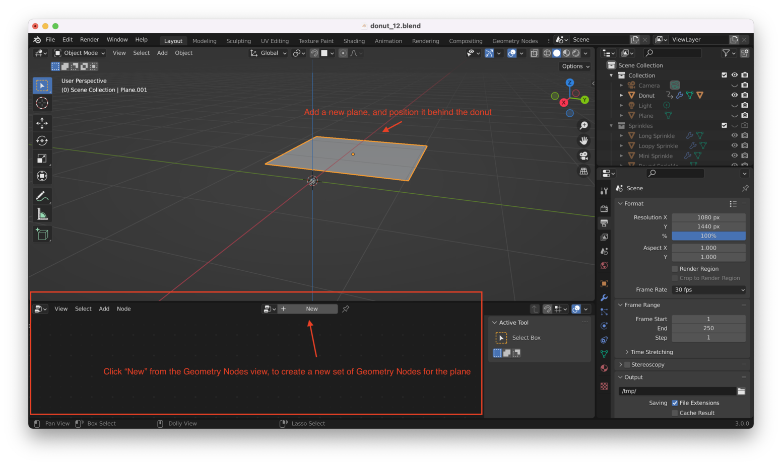
If you are still in the Animation view, click “Layout” on the top menu bar to return to the Layout view. Make sure the bottom pane in the Layout view is displaying Geometry Nodes.
Then, use “Shift + A” and choose “Mesh -> Plane” to create a new plane. Position it behind the donut as shown here:
Convert The Plane To A Set Of Points Link to heading
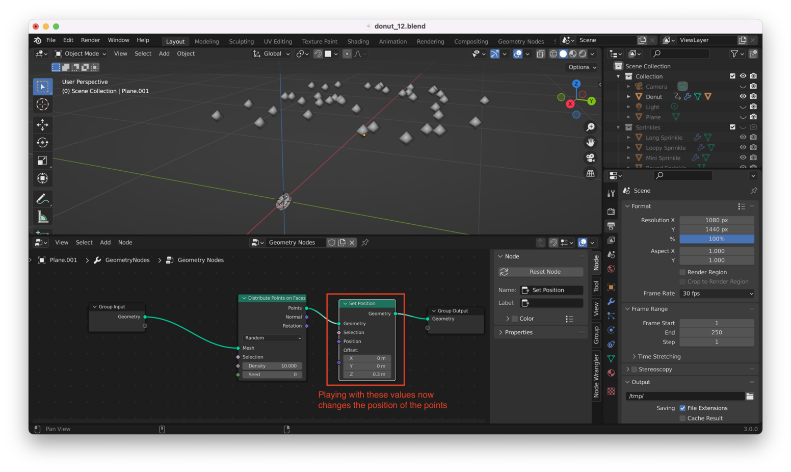
From the Geometry Node view, use “Shift + A” and choose “Point -> Distribute Points on Faces”. Place this new node between your “Group Input” and “Group Output”, like this:

Next, add a “Set Position” node. Again, this is done by hitting “Shift + A” within the Geometry Nodes view (bottom window), then choosing “Geometry -> Set Position”:
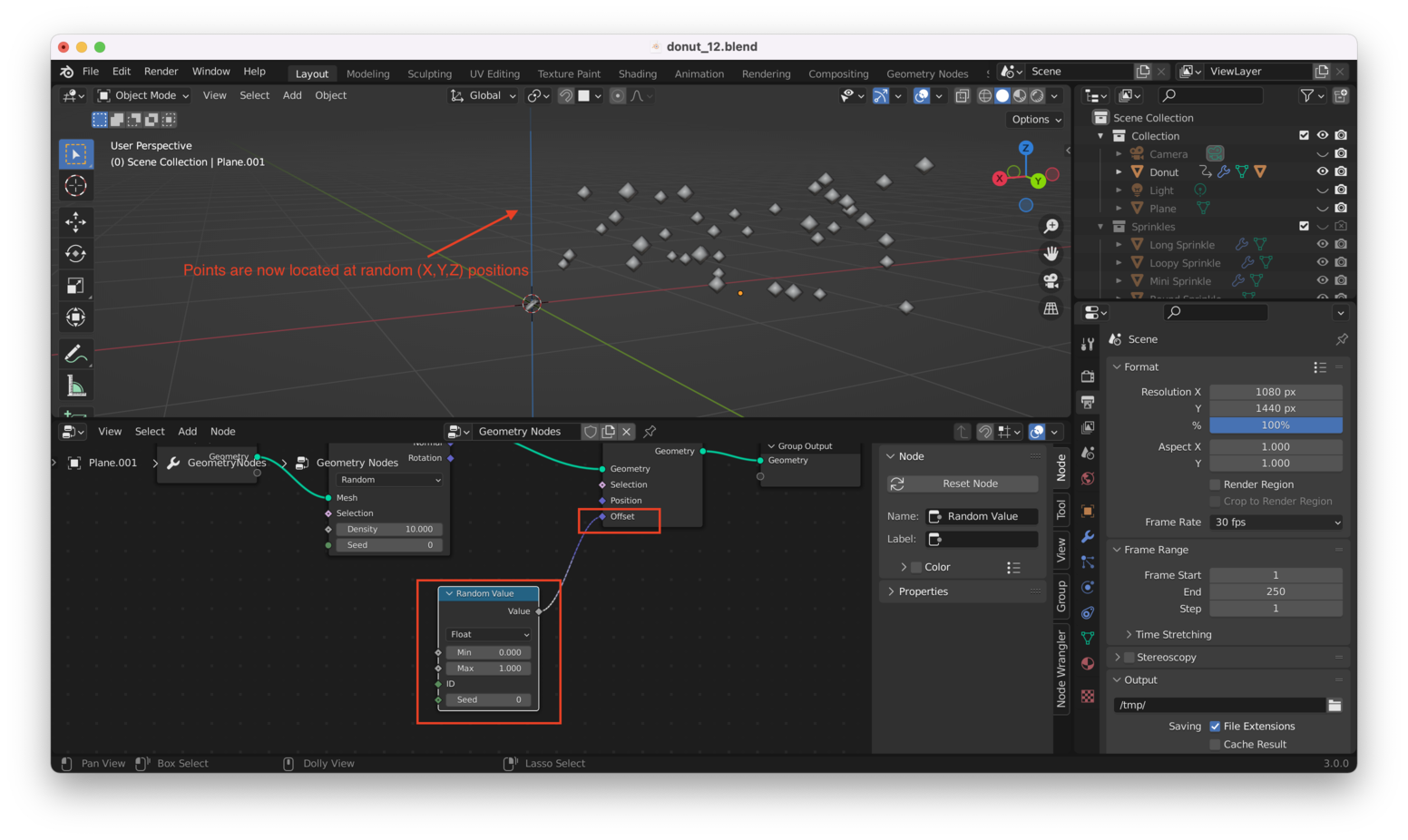
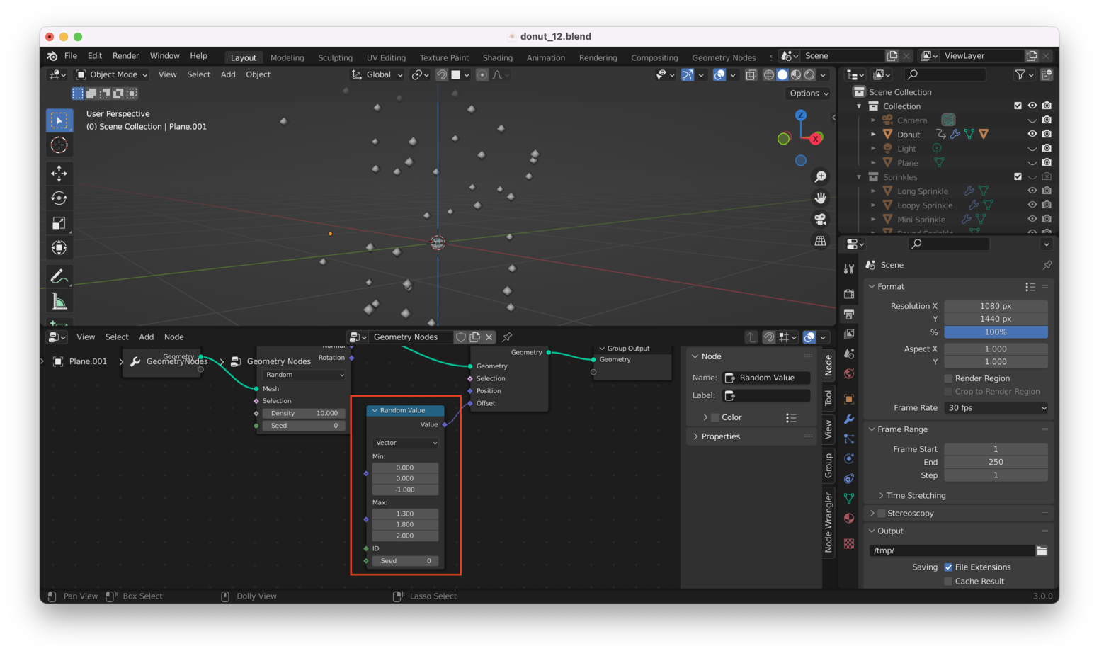
We want to randomize the position of our points, so again we’ll hit “Shift + A” then add a “Random Value” node, from “Utilities -> Random Value”:
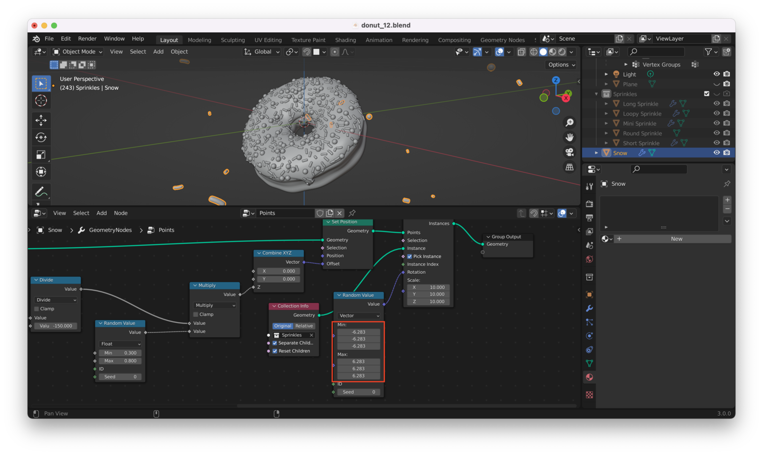
We don’t necessarily want our points distributed randomly in the same way along all three axes, so we’ll switch the output type of the “Random Value” node from “Float” to “Vector”:
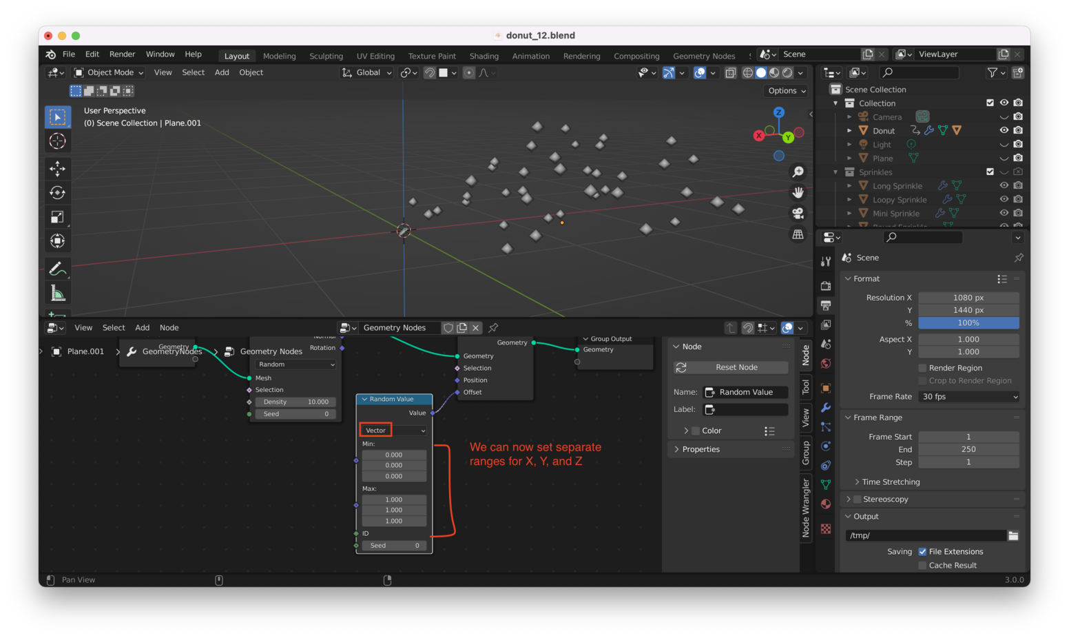
We can now adjust the minimum and maximum ranges separately for X, Y, and Z to get a distribution of points we like:
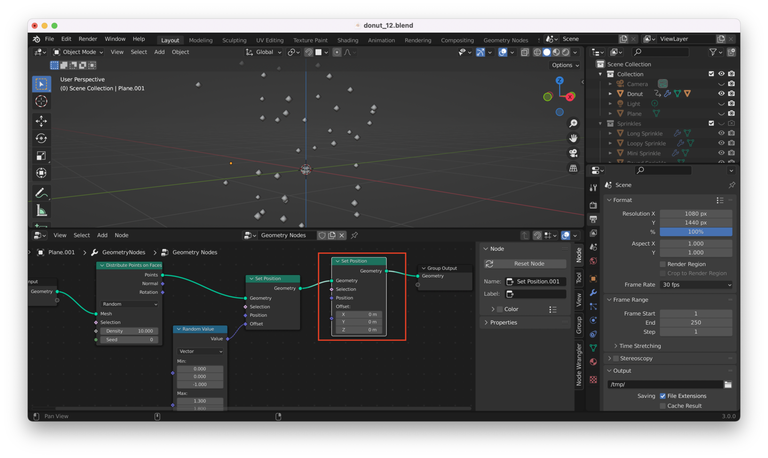
Make The Points “Fall” Link to heading
We want the points to drift downwards during our animation, almost like snow.
To do this, we will add another “Set Position” node, here:
Rather than manually setting up keyframes to get our points moving throughout the animation, we want to feed data about the current frame into our geometry nodes.
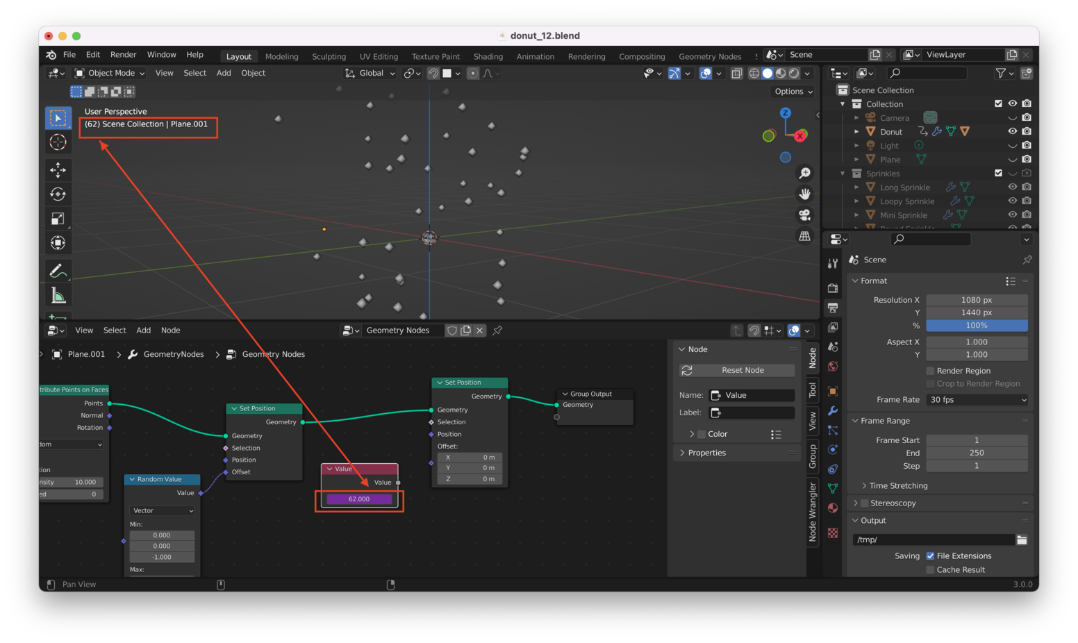
We do that by adding a “Value” node. From the Geometry Nodes view, hit “Shift + A” then choose “Input -> Value”:
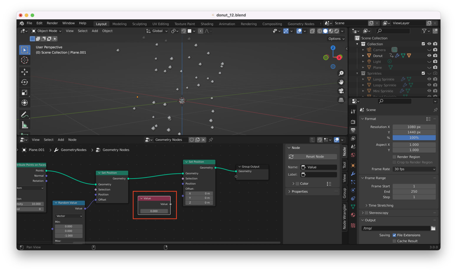
Typing #frame into the field on the Value node will cause the Value node to track the current frame in the animation, like this:
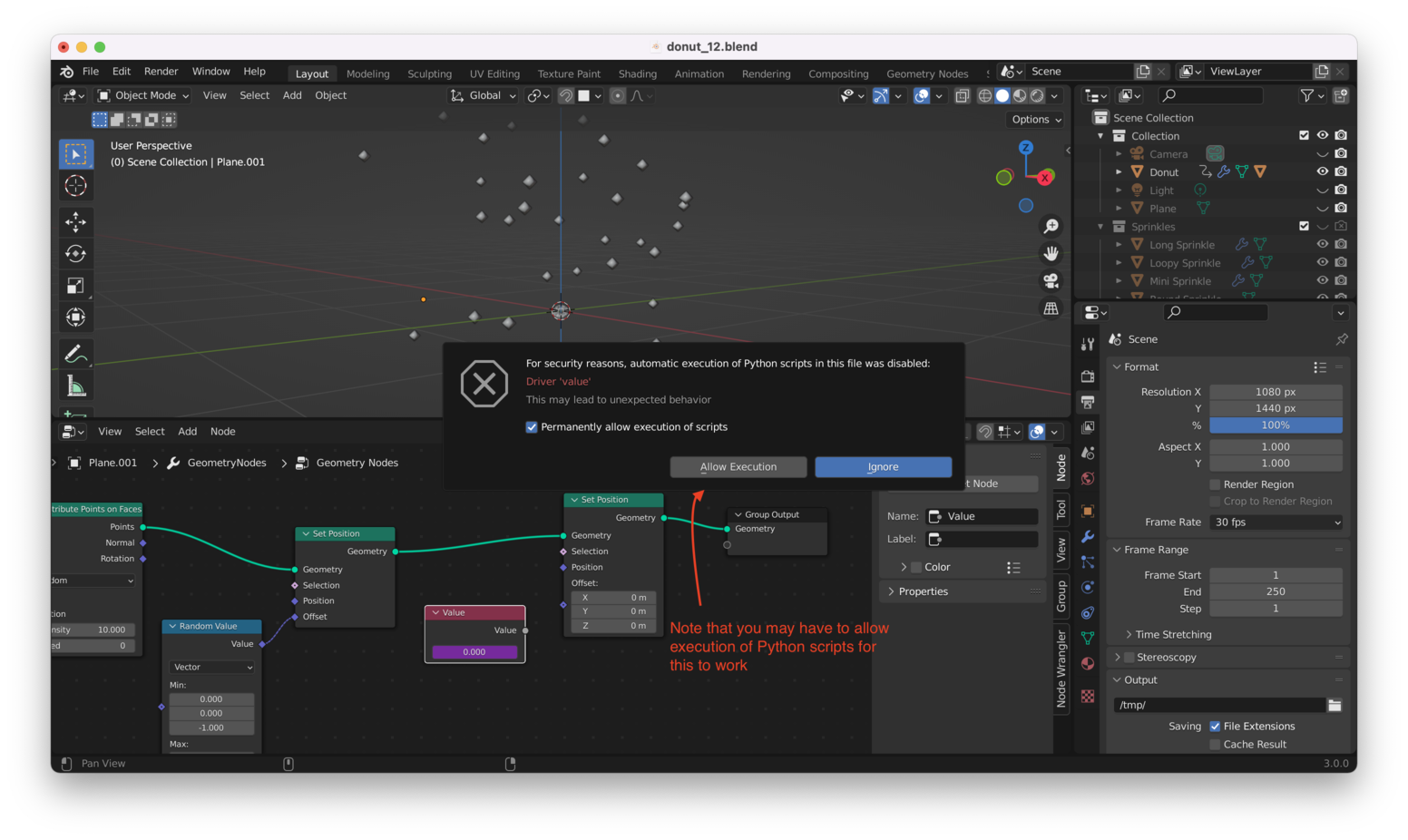
Tip: You may get a warning about executing Python scripts. For our purposes, it’s safe to tick the box that says “Permanently allow execution of scripts”, then click on “Allow Execution”. Just be careful to only run scripts you fully understand!
Note that after you allow execution of scripts, you may have to delete the Value node and then recreate it, before it starts properly tracking frames.
Hitting Spacebar to play our animation should now result in the “Value” node updating to display the current frame number, like this:
Of course, we can’t just drop this value directly into the “Offset” field in our second “Set Position” node. We need independent drivers for X, Y, and Z so we will add a “Combine XYZ” node, like this:
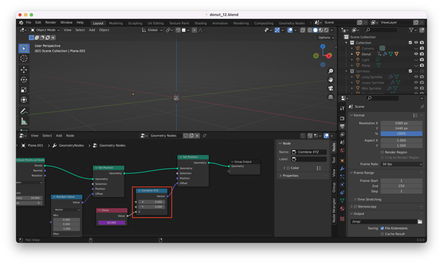
Note we’re using the “Value” node to drive the “Z” input on the “Combine XYZ” node, as we only need our points to appear to be moving downwards (along the Z-axis) during the animation.
We still have a problem, though: the points will move far too quickly if we drive their Z position directly using frame numbers.
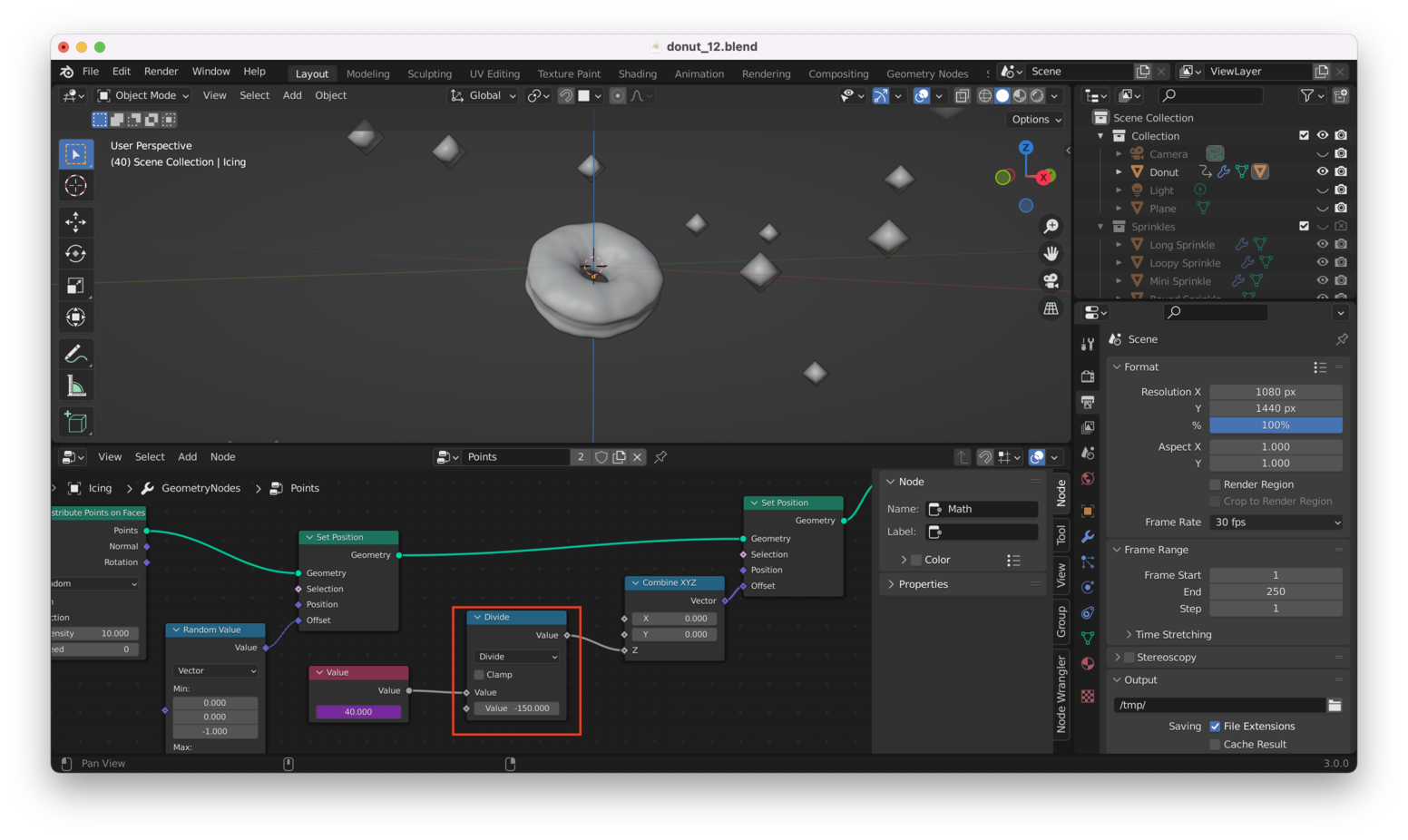
We’ll add a “Math” node to divide the values from the “Value” node in half, to reduce the distance our points are traveling during the animation. Like this:

Note that we used “Divide” here. We divide by 2, but choosing a larger number is also OK: this will cause our points to move downwards more slowly.
Tip: If your points appear to be moving upwards, not downwards, change the value in the “Divide” node to a negative number.
In my case, I decided on a final value of -150:
Of course, you can change this any time! That’s the beauty of Geometry Nodes.
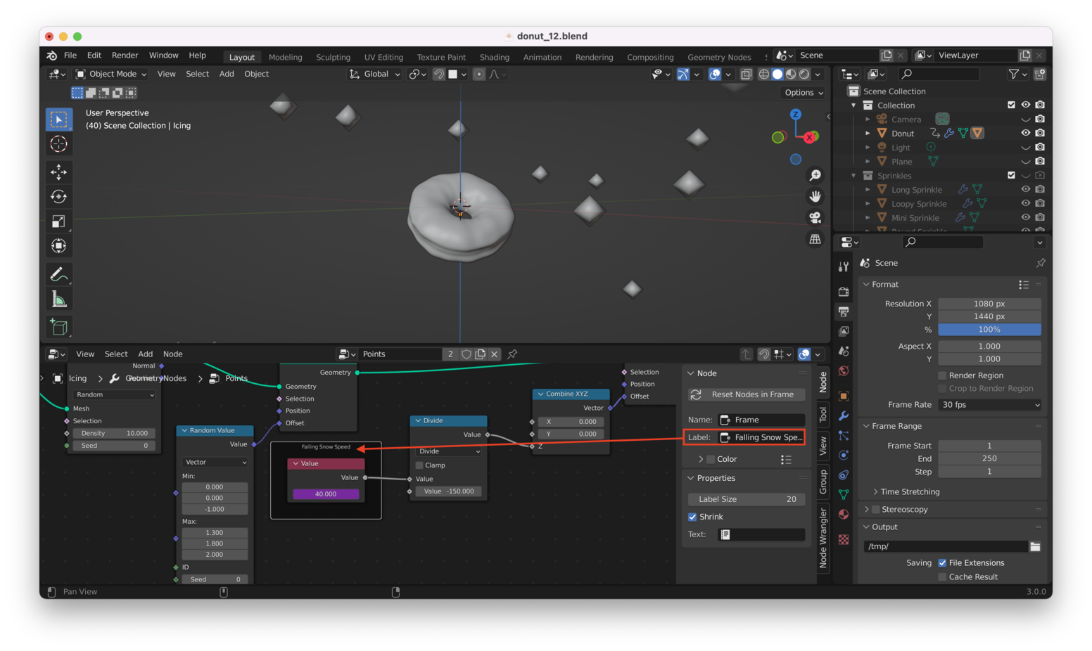
Tip: You can “comment” or “annotate” things in Blender. I can select my “Value” node and hit “Control + J” to add a “frame” around it. I can then write a comment in there.
Here’s a comment I added for the “Value” node using this method:
Make Particles Move Independently Link to heading
There’s still one key thing we haven’t done. We haven’t made the particles move at independent rates of speed! We’ll do this by adding a “Multiply” node and a “Random Value” node in sequence after our “Divide” node, like this:
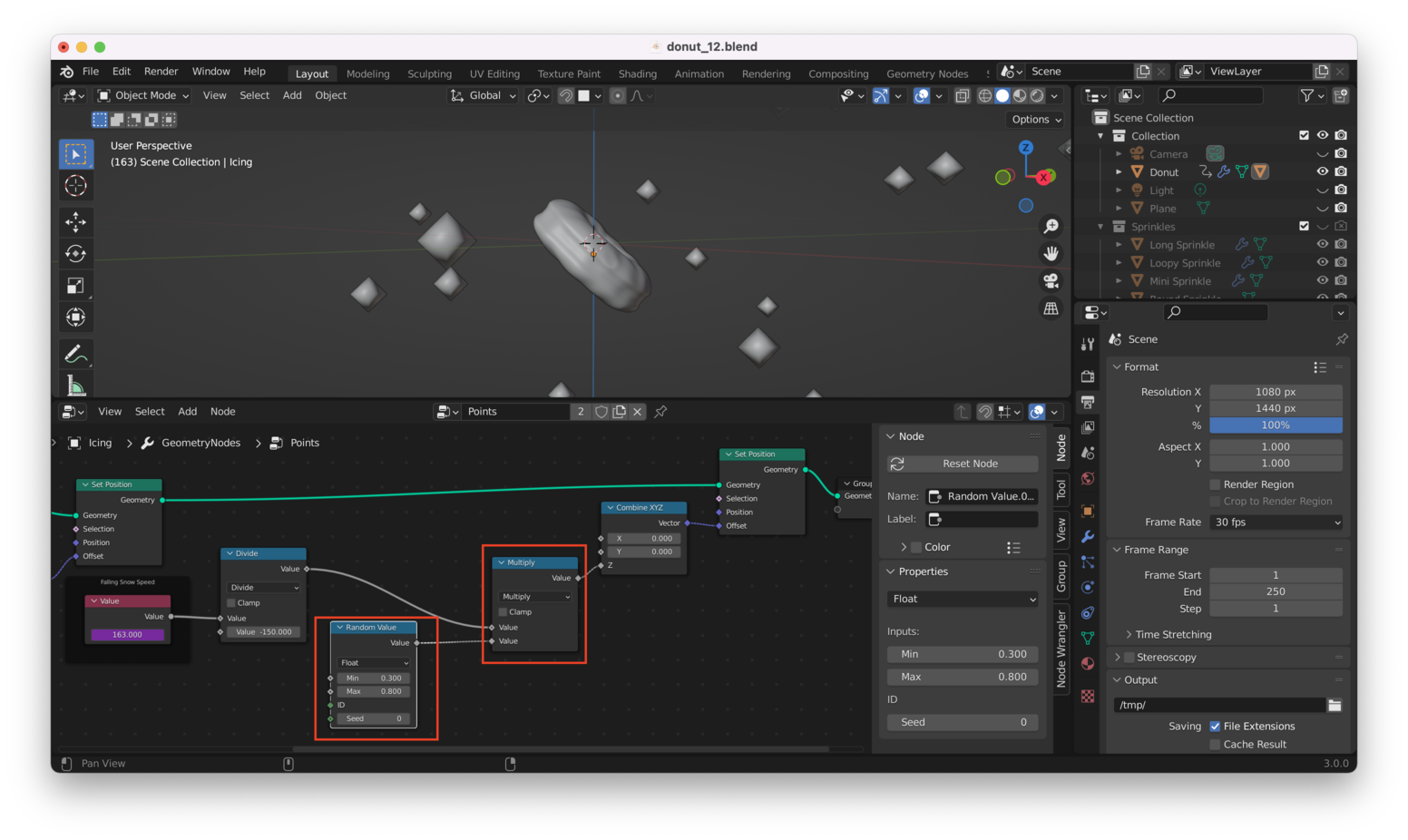
By playing with the minimum and maximum values at the “Random Value” node, we can now make each point fall at a different rate of speed!
Converting Our Particles Into Sprinkles Link to heading
Right now, our points don’t have any visual properties applied: if we rendered our scene right now, the points wouldn’t show up!
Let’s fix this by adding an “Instance on Points” node to the workflow, between the last “Set Position” node and the “Group Output” node, like this:
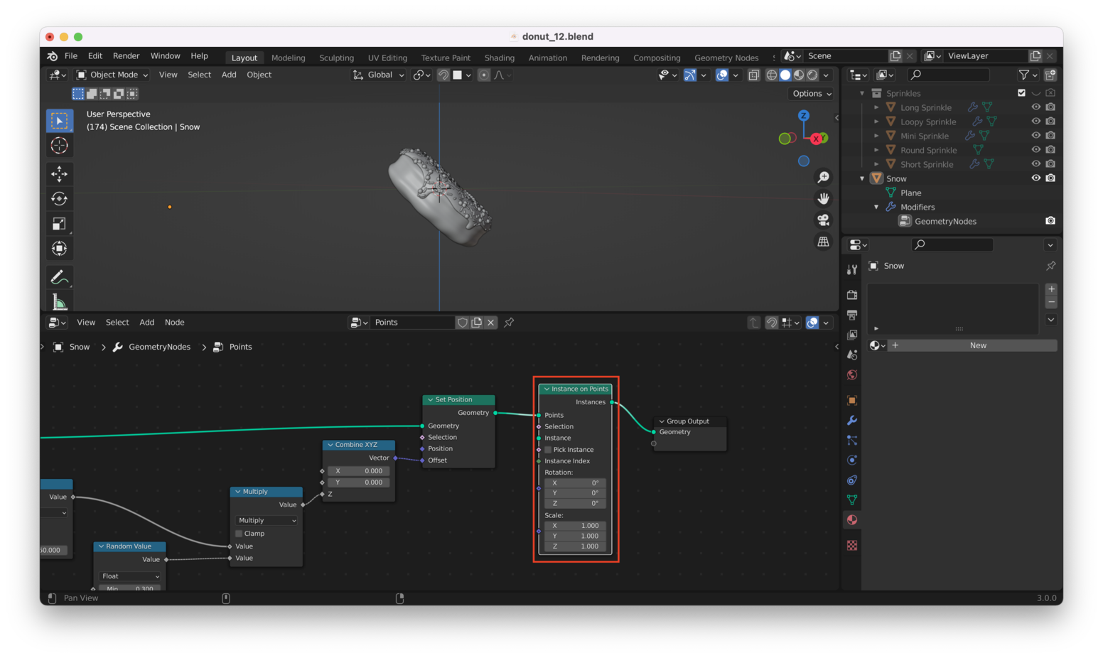
Note: It needs to be “Instance on Points” and not “Instances to Points”…they are different!
Doing this causes all of our points to disappear! Why? Because we haven’t chosen an object to map onto each point. We’ll use our sprinkles for this.
To do this, we add a “Collection Info” node, making sure to choose our “Sprinkles” collection and tick the boxes for “Separate Children” and “Reset Children”, as here:
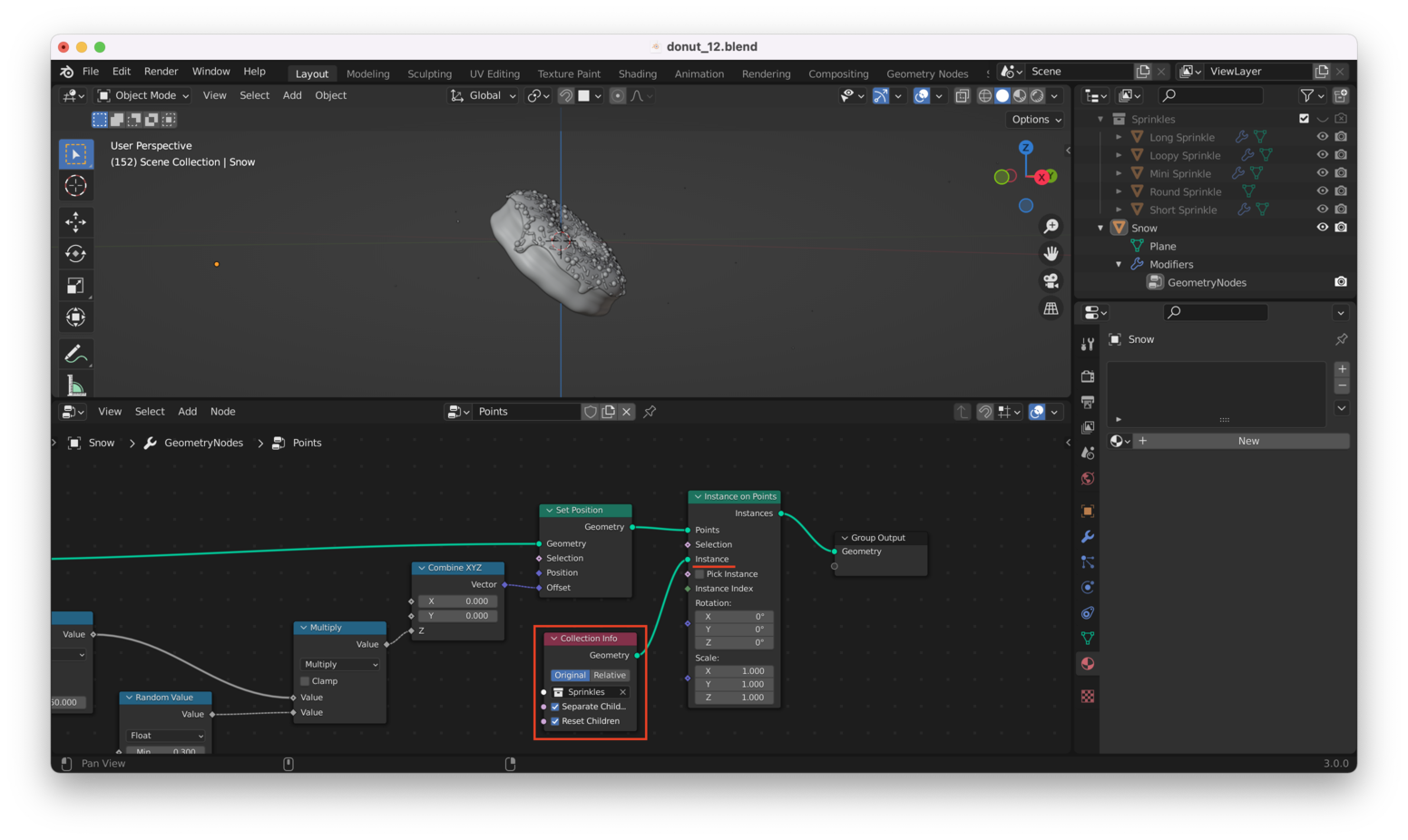
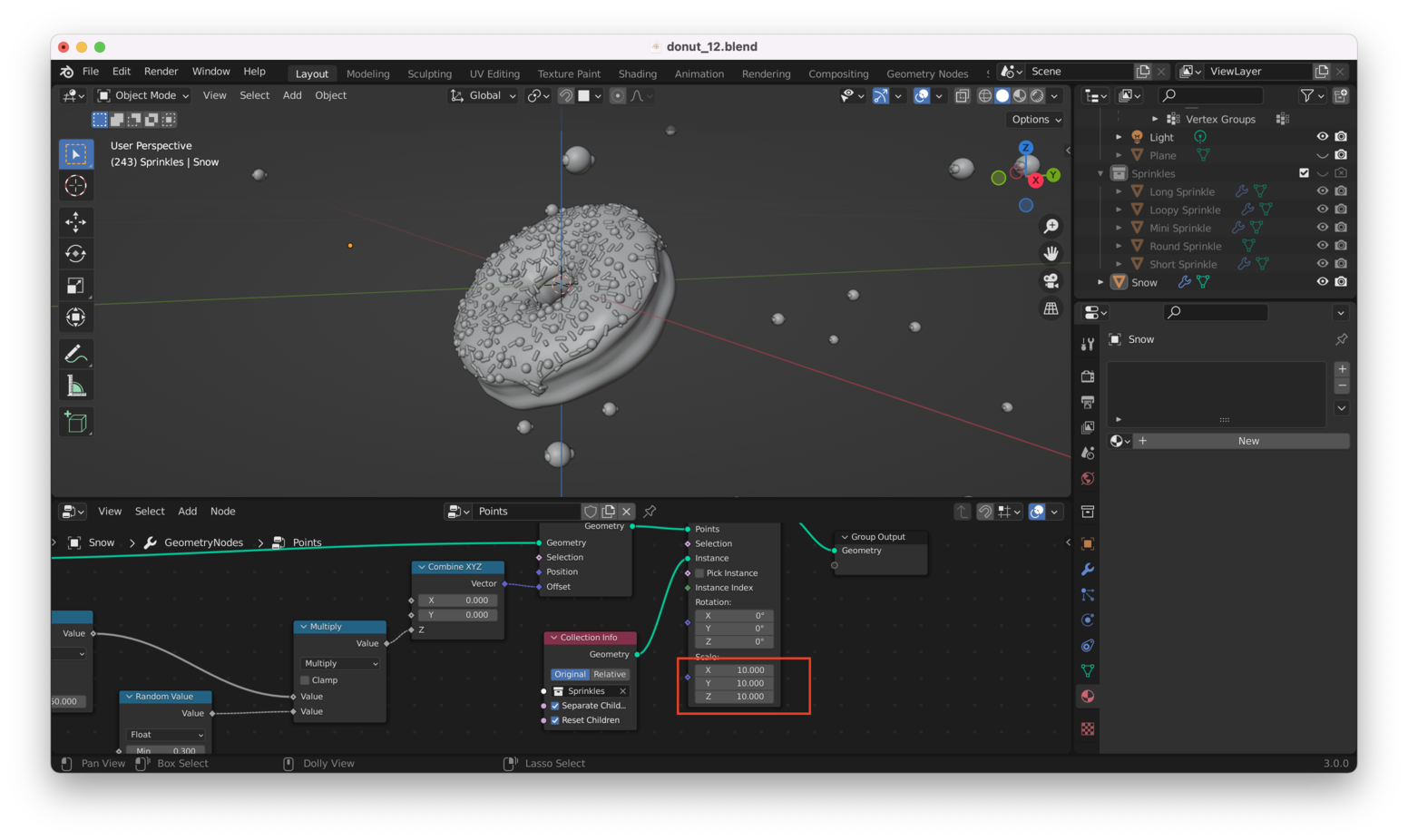
Ok, this works, but our sprinkles are so tiny we can barely see them:
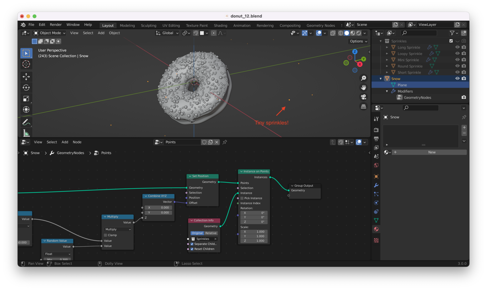
We can change the “Scale” values in the “Instance on Points” node to make them bigger:
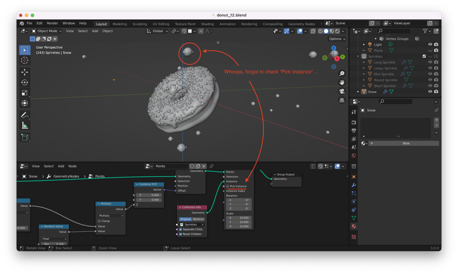
Note: If you get odd, “smushed together” sprinkles that appear to be a combination of all your sprinkles grouped one on top of the other (like I have here), then that means you forgot to check the “Pick Instance” box on the “Instance on Points” node:
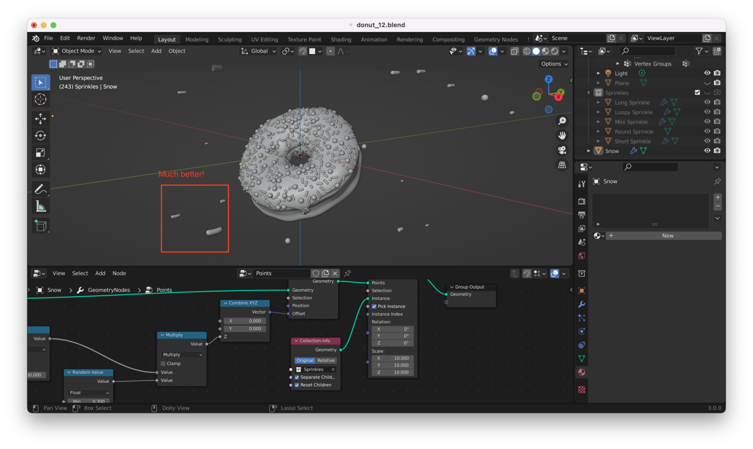
Checking that box should fix things:
Setting Random Rotations Link to heading
The sprinkles are all oriented the same way, which doesn’t look great, so it’s time to add another “Random Value” node, as here:
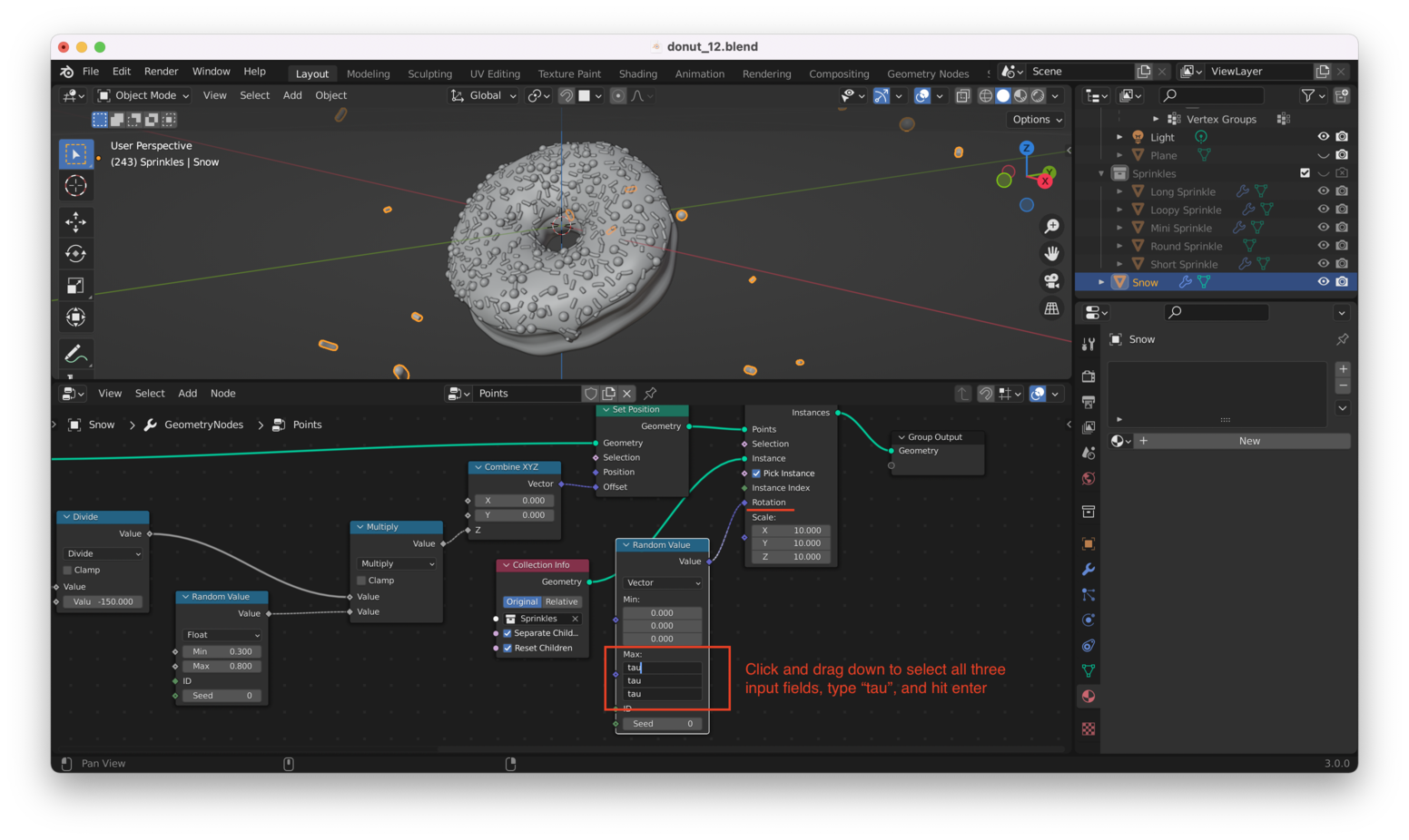
Now each sprinkle is oriented differently. You might want to set the “min” values to -tau for an even better effect, like this:
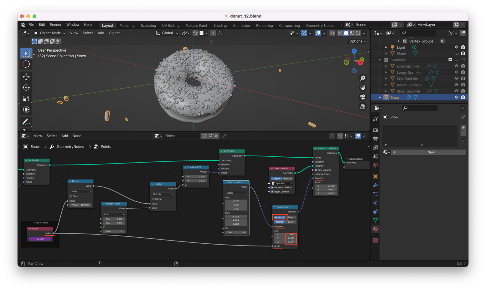
Great! We’re still not done, though. We want the sprinkles to rotate around during our animation. To achieve this, we can add a “Rotate Euler” node between our “Random Value” node and the “Instance on Points” node. We’ll drive the “Angle” input on that node using the “Value” node we created earlier: this is the same “Value” node we are using to drive the downward motion of our points (sprinkles).
Adding these nodes, we have:
Once again, directly using the frame number results in sprinkles that are flailing around wildly. We’ll add a “Math” node to slow things down:
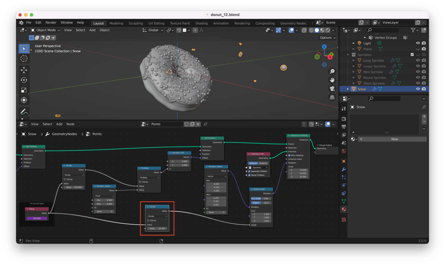
This works well: we get sprinkles that spin around at a reasonable rate as they fall.
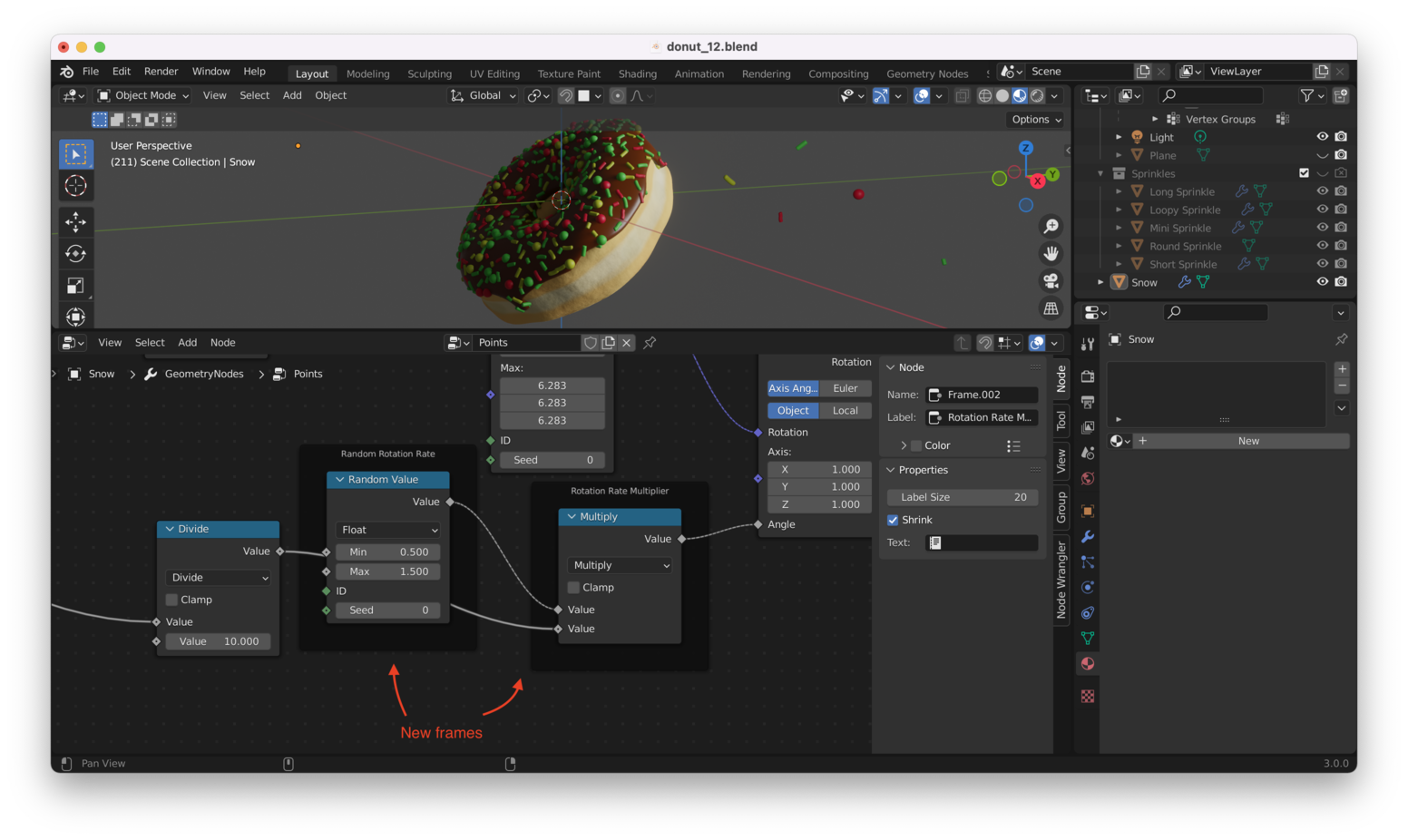
Right now, all the sprinkles rotate at the same speed: we want them to be moving at different speeds. This means we need to add another “Random Value” node and another “Math” node, producing a setup very similar to the one that alters the “fall rate” for our sprinkles. The resulting Geometry Node setup looks like this:
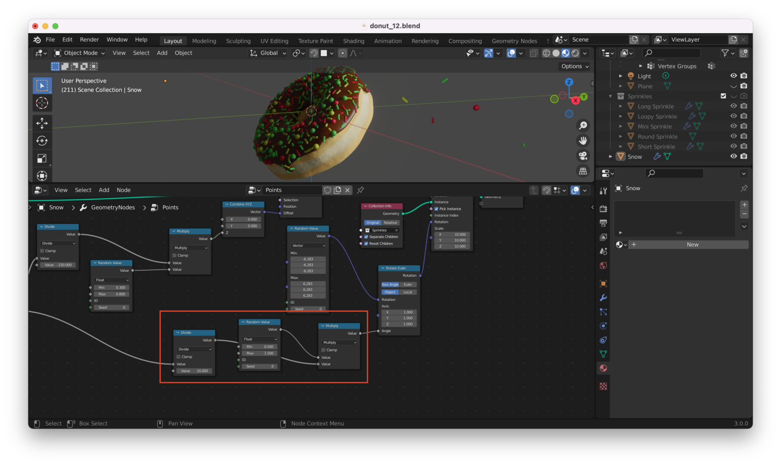
Let’s add some more “frames” to make it clear what’s going on.
Remember, selecting a node and hitting “Control + J” will allow you to add a frame:
Here’s a .gif animation, which should give you an idea what all these effects look like together:
Note: If you’re viewing the PDF version of this file, you won’t be able to see the
.gif. You can find it here: https://jeremypedersen.com/categories/blender-donut/Specifically, look for
Blender Donut Notes: 12at the link above
Other Stuff We Can Do Link to heading
You can play with the “Density” to set the overall number of sprinkles and play with the first “Random Value” box to determine the starting point and initial “geometry” for the cloud of sprinkles. Try it!
That’s all for this post!