Note: This is part of a series where I follow along with the ROS 2 Humble and Gazebo Fortress tutorials and demos. This is not original content.
Note: To follow along with today’s post, you need to have already installed Gazebo Fortress (and preferably also ROS 2 Humble). If you have not done this yet, check out this blog post.
In today’s post we’ll walk through the first few sections in the Gazebo fortress documentation, where we will learn how to build our own robot and place it into a simulated environment.
The blog will follow along with (and shamelessly borrow from) the official documentation.
Understanding SDF files Link to heading
Gazebo helps us simulate, visualize, and control virtual robots. To do this, Gazebo needs a way to describe and define objects and environments.
Gazebo does this with SDFormat (Simulation Description Format) files. SDF files are XML formatted documents describing both Gazebo “worlds” (simulated environments) and robots.
We will start out by creating a basic world using the building_robot.sdf file provided in the docs. Save this somewhere on your machine:
<?xml version="1.0" ?>
<sdf version="1.8">
    <world name="car_world">
        <physics name="1ms" type="ignored">
            <max_step_size>0.001</max_step_size>
            <real_time_factor>1.0</real_time_factor>
        </physics>
        <plugin
            filename="libignition-gazebo-physics-system.so"
            name="ignition::gazebo::systems::Physics">
        </plugin>
        <plugin
            filename="libignition-gazebo-user-commands-system.so"
            name="ignition::gazebo::systems::UserCommands">
        </plugin>
        <plugin
            filename="libignition-gazebo-scene-broadcaster-system.so"
            name="ignition::gazebo::systems::SceneBroadcaster">
        </plugin>

        <light type="directional" name="sun">
            <cast_shadows>true</cast_shadows>
            <pose>0 0 10 0 0 0</pose>
            <diffuse>0.8 0.8 0.8 1</diffuse>
            <specular>0.2 0.2 0.2 1</specular>
            <attenuation>
                <range>1000</range>
                <constant>0.9</constant>
                <linear>0.01</linear>
                <quadratic>0.001</quadratic>
            </attenuation>
            <direction>-0.5 0.1 -0.9</direction>
        </light>

        <model name="ground_plane">
            <static>true</static>
            <link name="link">
                <collision name="collision">
                <geometry>
                    <plane>
                    <normal>0 0 1</normal>
                    </plane>
                </geometry>
                </collision>
                <visual name="visual">
                <geometry>
                    <plane>
                    <normal>0 0 1</normal>
                    <size>100 100</size>
                    </plane>
                </geometry>
                <material>
                    <ambient>0.8 0.8 0.8 1</ambient>
                    <diffuse>0.8 0.8 0.8 1</diffuse>
                    <specular>0.8 0.8 0.8 1</specular>
                </material>
                </visual>
            </link>
        </model>
    </world>
</sdf>
Great! Once you’ve got that copied in, you can open up Gazebo and view the new world with the following command:
ign gazebo building_robot.sdf
Note: Your file doesn’t have to be named building_robot.sdf. Any name will do. You could just as easily name it my_world.sdf.
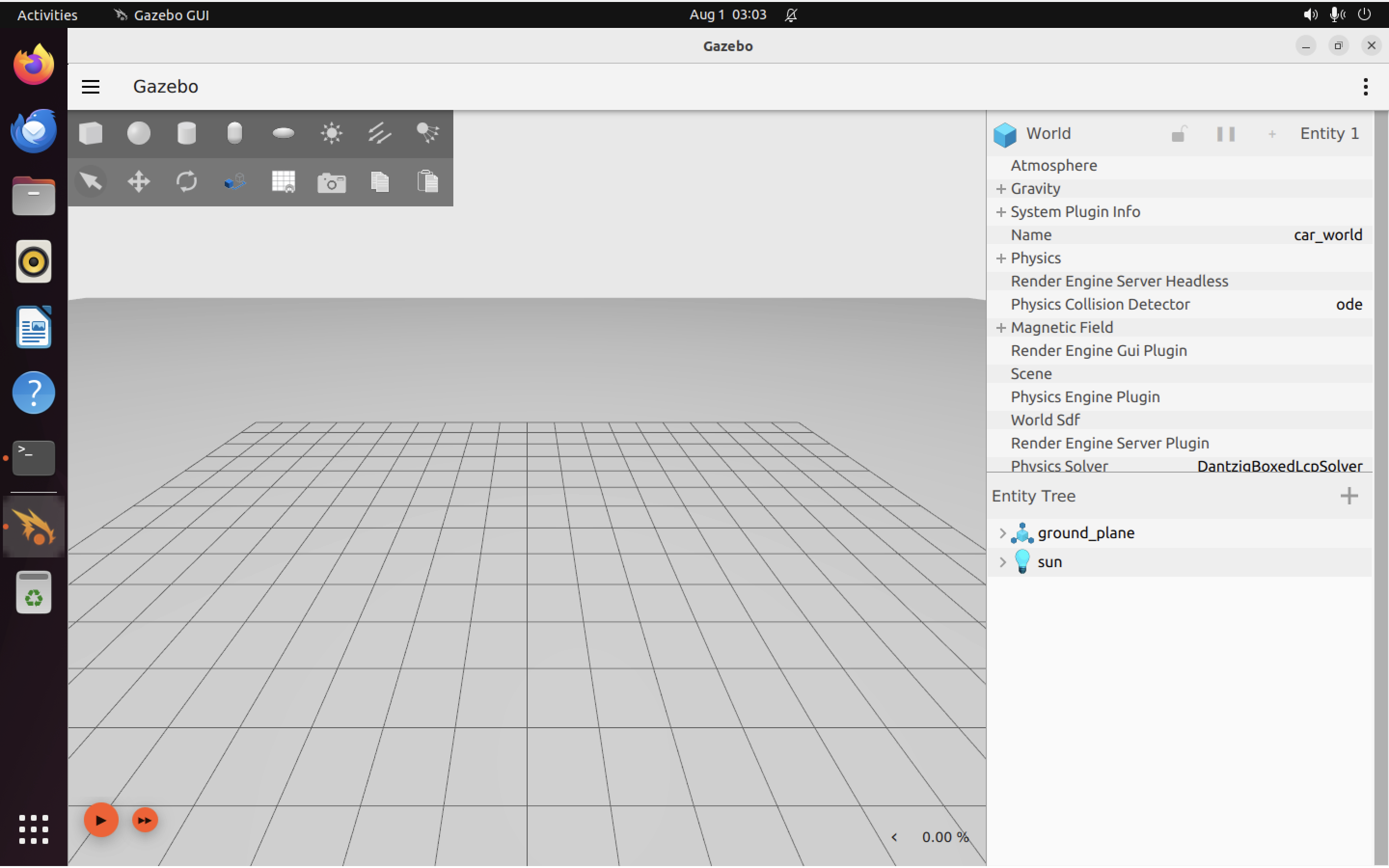
You’ll see an empty world with a single light source (the “sun”):
Next, we need to start building our robot. Close gazebo and open up your .sdf file in your favorite text editor.
Creating a robot Link to heading
Notice how the SDF file contains several <model> tags. We’ll add another one just above </world>, to represent our robot.
First, we need to name it and give it a “pose” (orientation and position) relative to the rest of the world:
<model name='vehicle_blue' canonical_link='chassis'>
    <pose relative_to='world'>0 0 0 0 0 0</pose>
It should have a unique name. It should also have a “canonical_link” defined. This is the link that the model’s “implicit frame” is attached to. If you don’t explicitly define one, the first <link> tag inside the <model> is automatically chosen as the canonical link.
Similarly, with <pose> you need to specify what other frame (such as the world) the pose is relative to. If you don’t specify, then the “world” will be chosen, by default.
Adding links Link to heading
In Gazebo, every robot is made up of one or more links joined together by joints.
Let’s add our first link, the robot’s body (chassis):
<link name='chassis'>
    <pose relative_to='__model__'>0.5 0 0.4 0 0 0</pose>
Great, but we still haven’t defined how this body component should move (i.e. what is its mass? inertia?). We do that with an <inertial> tag, like this:
<inertial> <!--inertial properties of the link mass, inertia matix-->
    <mass>1.14395</mass>
    <inertia>
        <ixx>0.095329</ixx>
        <ixy>0</ixy>
        <ixz>0</ixz>
        <iyy>0.381317</iyy>
        <iyz>0</iyz>
        <izz>0.476646</izz>
    </inertia>
</inertial>
There’s a handy calculator (for primitive shapes only) here, if you aren’t sure what the moment of inertia should be for a given component of your robot.
We also need to make sure our robot’s body will actually appear (be visible) in the simulation and we want to give it an actual shape and size, so that we can calculate whether or not it has collided with anything. We add a visual component (a blue box) with:
<visual name='visual'>
    <geometry>
        <box>
            <size>2.0 1.0 0.5</size>
        </box>
    </geometry>
    <!--let's add color to our link-->
    <material>
        <ambient>0.0 0.0 1.0 1</ambient>
        <diffuse>0.0 0.0 1.0 1</diffuse>
        <specular>0.0 0.0 1.0 1</specular>
    </material>
</visual>
And a collision model (a simple box) with:
        <collision name='collision'>
            <geometry>
                <box>
                    <size>2.0 1.0 0.5</size>
                </box>
            </geometry>
        </collision>
    </link>
</model>
Notice that we have now closed out the </model> tag. We have just enough for a robot that can actually be simulated in Gazebo. To sum up, here is the full robot model, as we have defined it so far:
<model name='vehicle_blue' canonical_link='chassis'>
    <pose relative_to='world'>0 0 0 0 0 0</pose>
    <link name='chassis'>
        <pose relative_to='__model__'>0.5 0 0.4 0 0 0</pose>
        <inertial> <!--inertial
            properties of the link mass, inertia matix-->
            <mass>1.14395</mass>
            <inertia>
                <ixx>0.095329</ixx>
                <ixy>0</ixy>
                <ixz>0</ixz>
                <iyy>0.381317</iyy>
                <iyz>0</iyz>
                <izz>0.476646</izz>
            </inertia>
        </inertial>
        <visual name='visual'>
            <geometry>
                <box>
                    <size>2.0 1.0 0.5</size>
                </box>
            </geometry>
            <!--let's
            add color to our link-->
            <material>
                <ambient>0.0 0.0 1.0 1</ambient>
                <diffuse>0.0 0.0 1.0 1</diffuse>
                <specular>0.0 0.0 1.0 1</specular>
            </material>
        </visual>
        <collision name='collision'>
            <geometry>
                <box>
                    <size>2.0 1.0 0.5</size>
                </box>
            </geometry>
        </collision>
    </link>
</model>
Make sure your code matches, and then re-run:
ign gazebo building_robot.sdf
You should now see a blue box:
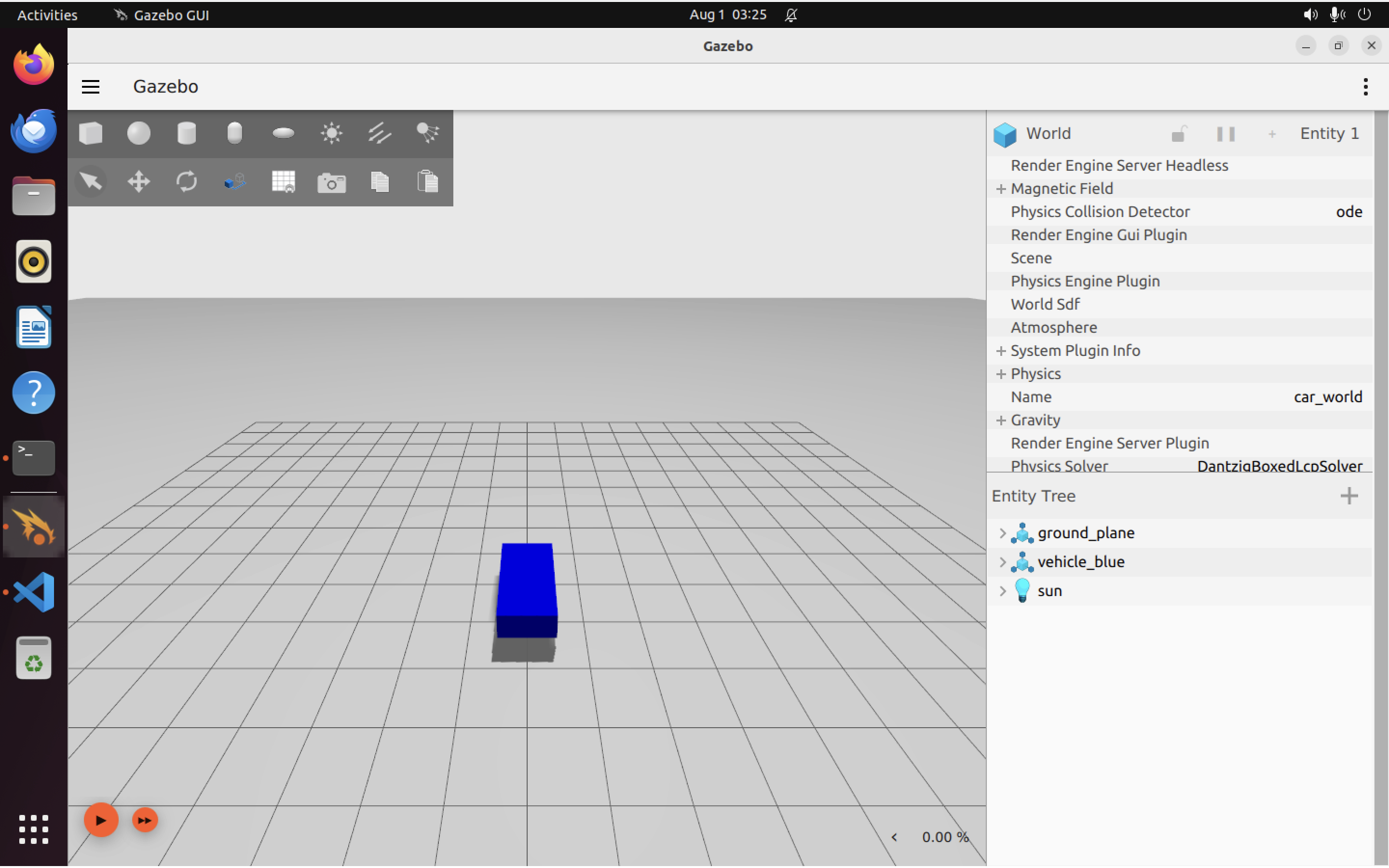
If you click on the “translate” tool in the top left, you’ll see X (red), Y (green), and Z (blue) axis markers appear around the box, which will let you drag the car around in the X, Y, or Z direction.
Adding wheels Link to heading
Now we need to start adding wheels. Again, for each component (<link>) that we add to our robot, we will need to define:
- Its pose relative to some other component (in this case the chassis)
- Its inertial properties
- Its visual properties
- Its collision properties
- Its joints (connections to other links)
We’re going to end up adding 3 wheels to our robot:
- A rear left wheel (ordinary wheel)
- A rear right wheel (ordinary wheel)
- A single front wheel under the body (a “caster wheel”, like on an office chair or grocery cart)
Ok, let’s get started on all that.
First, we add the left wheel. To save time I reproduce the completed code here (including inertial, visual, and collision components). You can copy-paste this right into your .sdf file below the chassis <link>:
<link name='left_wheel'>
    <pose relative_to="chassis">-0.5 0.6 0 -1.5707 0 0</pose>
    <inertial>
        <mass>1</mass>
        <inertia>
            <ixx>0.043333</ixx>
            <ixy>0</ixy>
            <ixz>0</ixz>
            <iyy>0.043333</iyy>
            <iyz>0</iyz>
            <izz>0.08</izz>
        </inertia>
    </inertial>
    <visual name='visual'>
        <geometry>
            <cylinder>
                <radius>0.4</radius>
                <length>0.2</length>
            </cylinder>
        </geometry>
        <material>
            <ambient>1.0 0.0 0.0 1</ambient>
            <diffuse>1.0 0.0 0.0 1</diffuse>
            <specular>1.0 0.0 0.0 1</specular>
        </material>
    </visual>
    <collision name='collision'>
        <geometry>
            <cylinder>
                <radius>0.4</radius>
                <length>0.2</length>
            </cylinder>
        </geometry>
    </collision>
</link>
Notice how the pose is defined relative to the chassis, rather than relative to the world. This makes sense, as the wheels are sub-components of the robot itself.
Now, the right wheel (same properties but differrent pose relative to the chassis, as it’s on the other side of the chassis from the left wheel, of course):
<!--The same as left wheel but with different position-->
<link name='right_wheel'>
    <pose relative_to="chassis">-0.5 -0.6 0 -1.5707 0 0</pose> <!--angles are in radian-->
    <inertial>
        <mass>1</mass>
        <inertia>
            <ixx>0.043333</ixx>
            <ixy>0</ixy>
            <ixz>0</ixz>
            <iyy>0.043333</iyy>
            <iyz>0</iyz>
            <izz>0.08</izz>
        </inertia>
    </inertial>
    <visual name='visual'>
        <geometry>
            <cylinder>
                <radius>0.4</radius>
                <length>0.2</length>
            </cylinder>
        </geometry>
        <material>
            <ambient>1.0 0.0 0.0 1</ambient>
            <diffuse>1.0 0.0 0.0 1</diffuse>
            <specular>1.0 0.0 0.0 1</specular>
        </material>
    </visual>
    <collision name='collision'>
        <geometry>
            <cylinder>
                <radius>0.4</radius>
                <length>0.2</length>
            </cylinder>
        </geometry>
    </collision>
</link>
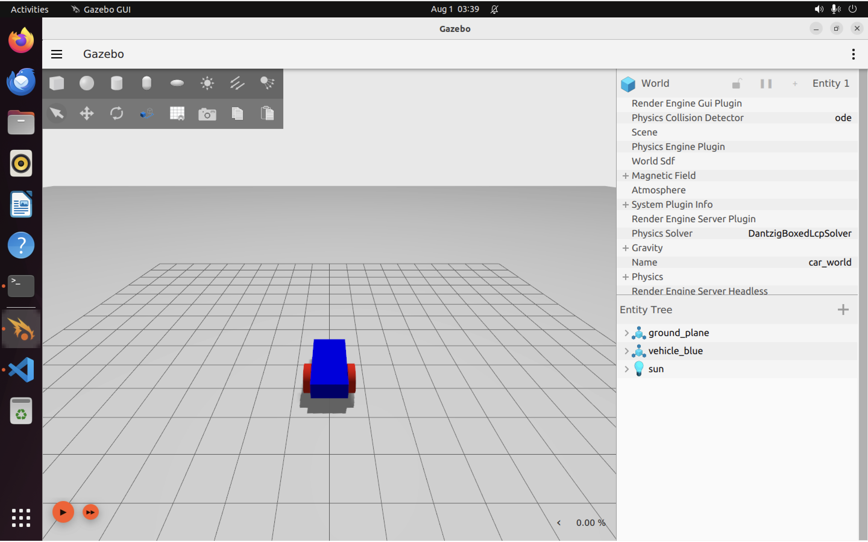
Save your .sdf, and let’s take a quick peek at our robot to see how it’s shaping up:
ign gazebo building_robot.sdf
Which should give you something like this:
In SDF v1.7 and above (Gazebo Fortress uses SDF v1.8) we can also define arbitrary frames. Let’s use one for our front (caster) wheel:
<frame name="caster_frame" attached_to='chassis'>
    <pose>0.8 0 -0.2 0 0 0</pose>
</frame>
Note that we didn’t use relative_to. This frame is going to be relative to the chassis link, because that’s what it is attached to.
Below this <frame> tag, we add the code for the caster wheel itself:
<!--caster wheel-->
<link name='caster'>
    <pose relative_to='caster_frame'/>
    <inertial>
        <mass>1</mass>
        <inertia>
            <ixx>0.016</ixx>
            <ixy>0</ixy>
            <ixz>0</ixz>
            <iyy>0.016</iyy>
            <iyz>0</iyz>
            <izz>0.016</izz>
        </inertia>
    </inertial>
    <visual name='visual'>
        <geometry>
            <sphere>
                <radius>0.2</radius>
            </sphere>
        </geometry>
        <material>
            <ambient>0.0 1 0.0 1</ambient>
            <diffuse>0.0 1 0.0 1</diffuse>
            <specular>0.0 1 0.0 1</specular>
        </material>
    </visual>
    <collision name='collision'>
        <geometry>
            <sphere>
                <radius>0.2</radius>
            </sphere>
        </geometry>
    </collision>
</link>
Notice how we did not specify a pose inside the <pose> tag. This is because we don’t need to: the pose will be relative to the new caster_frame we defined earlier.
Our caster wheel is a simple ball, so we have defined it as a sphere (both for visual and collision purposes).
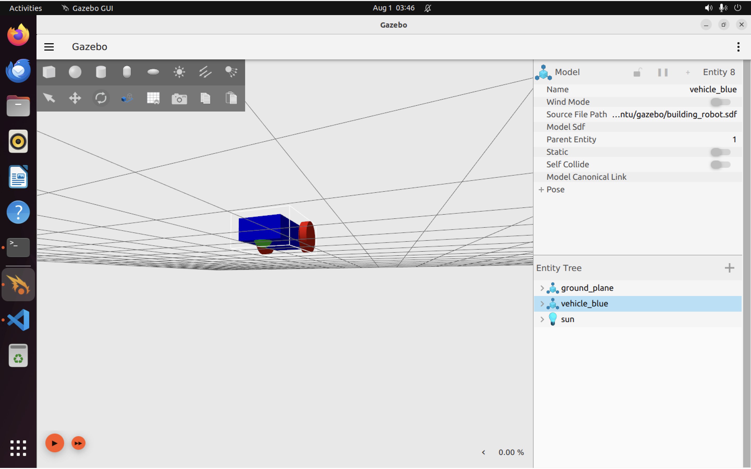
We can open up Gazebo again and rotate things around a bit to see our new wheel (it’s on the bottom of the car, near the front):
ign gazebo building_robot.sdf
Here it is:
Creating joints Link to heading
We’ve got all the components of our basic robot, but they aren’t linked together. Let’s fix that by adding joints. Using the <joint> tag, we will:
- Define which links are connected
- Define how these links should move relative to each other
Here’s the complete code for the left wheel joint:
<joint name='left_wheel_joint' type='revolute'>
    <pose relative_to='left_wheel'/>
    <parent>chassis</parent>
    <child>left_wheel</child>
    <axis>
        <xyz expressed_in='__model__'>0 1 0</xyz> <!--can be defined as any frame or even arbitrary frames-->
        <limit>
            <lower>-1.79769e+308</lower>    <!--negative infinity-->
            <upper>1.79769e+308</upper>     <!--positive infinity-->
        </limit>
    </axis>
</joint>
Some important points about the code above:
- Every joint needs to connect two links (bodies together). Here, we link the left_wheel (child) to the chassis (parent).
- Joints have types. Here the type is
revolutewhich means the joint has one rotational degree of freedom (can rotate about one axis). revolutejoins must have upper and lower ranges to express how far the joint can rotate. A wheel should be able to rotate forever, so we set the<upper>and<lower>ranges to positive and negative infinity.- We can define the axis of rotation relative to any frame, but here it’s set relative to
model, which means the axis we rotate around is theyaxis, hence the<xyz>tag is set to0 1 0meaning rotation about theyaxis.
And for the right wheel joint, very similar code:
<joint name='right_wheel_joint' type='revolute'>
    <pose relative_to='right_wheel'/>
    <parent>chassis</parent>
    <child>right_wheel</child>
    <axis>
        <xyz expressed_in='__model__'>0 1 0</xyz>
        <limit>
            <lower>-1.79769e+308</lower>    <!--negative infinity-->
            <upper>1.79769e+308</upper>     <!--positive infinity-->
        </limit>
    </axis>
</joint>
We also need a joint for the caster wheel. Surprisingly, this turns out to be the simplest joint because the joint type ball (which we can use because our caster wheel is a sphere) doesn’t require us to define any rotational degrees of freedom or ranges of rotation. Makes sense, given that a ball can roll about infinitely along any axis.
<joint name='caster_wheel' type='ball'>
    <parent>chassis</parent>
    <child>caster</child>
</joint>
With all these joints and links defined, we can take a last look at our completed robot (although the joints are not visual components, so you should not see any visible differences):
ign gazebo building_robot.sdf
Which shows:
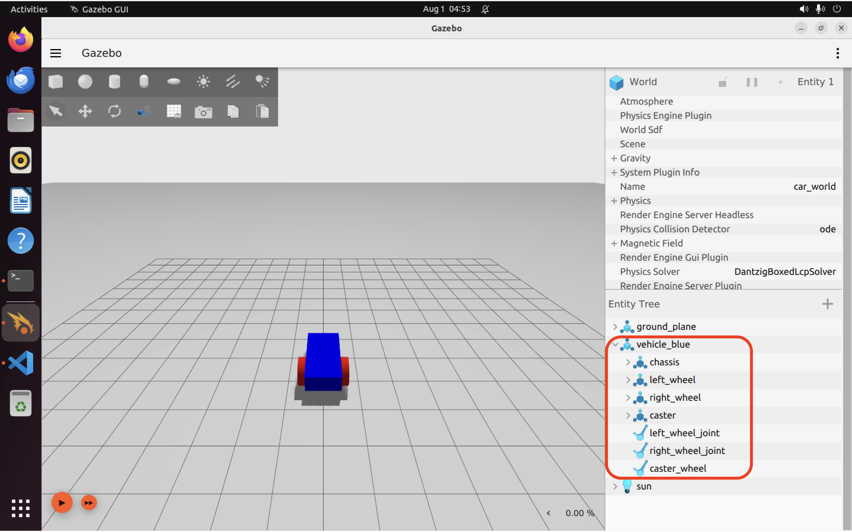
Again there’s no change in the robot’s appearance, but if you expand the entity tree you can see the new joints and wheels.
Completed building_robot.sdf file
Link to heading
Here’s the completed file. We’ll add to it in future tutorials, where we will look at other things like moving the robot and adding sensors.
<?xml version="1.0"?>
<sdf version="1.8">
    <world name="car_world">
        <physics name="1ms" type="ignored">
            <max_step_size>0.001</max_step_size>
            <real_time_factor>1.0</real_time_factor>
        </physics>
        <plugin
            filename="libignition-gazebo-physics-system.so"
            name="ignition::gazebo::systems::Physics">
        </plugin>
        <plugin
            filename="libignition-gazebo-user-commands-system.so"
            name="ignition::gazebo::systems::UserCommands">
        </plugin>
        <plugin
            filename="libignition-gazebo-scene-broadcaster-system.so"
            name="ignition::gazebo::systems::SceneBroadcaster">
        </plugin>

        <light type="directional" name="sun">
            <cast_shadows>true</cast_shadows>
            <pose>0 0 10 0 0 0</pose>
            <diffuse>0.8 0.8 0.8 1</diffuse>
            <specular>0.2 0.2 0.2 1</specular>
            <attenuation>
                <range>1000</range>
                <constant>0.9</constant>
                <linear>0.01</linear>
                <quadratic>0.001</quadratic>
            </attenuation>
            <direction>-0.5 0.1 -0.9</direction>
        </light>

        <model name="ground_plane">
            <static>true</static>
            <link name="link">
                <collision name="collision">
                    <geometry>
                        <plane>
                            <normal>0 0 1</normal>
                        </plane>
                    </geometry>
                </collision>
                <visual name="visual">
                    <geometry>
                        <plane>
                            <normal>0 0 1</normal>
                            <size>100 100</size>
                        </plane>
                    </geometry>
                    <material>
                        <ambient>0.8 0.8 0.8 1</ambient>
                        <diffuse>0.8 0.8 0.8 1</diffuse>
                        <specular>0.8 0.8 0.8 1</specular>
                    </material>
                </visual>
            </link>
        </model>
        <model name='vehicle_blue' canonical_link='chassis'>
            <pose relative_to='world'>0 0 0 0 0 0</pose>
            <link name='chassis'>
                <pose relative_to='__model__'>0.5 0 0.4 0 0 0</pose>
                <inertial> <!--inertial
                    properties of the link mass, inertia matix-->
                    <mass>1.14395</mass>
                    <inertia>
                        <ixx>0.095329</ixx>
                        <ixy>0</ixy>
                        <ixz>0</ixz>
                        <iyy>0.381317</iyy>
                        <iyz>0</iyz>
                        <izz>0.476646</izz>
                    </inertia>
                </inertial>
                <visual name='visual'>
                    <geometry>
                        <box>
                            <size>2.0 1.0 0.5</size>
                        </box>
                    </geometry>
                    <!--let's
                    add color to our link-->
                    <material>
                        <ambient>0.0 0.0 1.0 1</ambient>
                        <diffuse>0.0 0.0 1.0 1</diffuse>
                        <specular>0.0 0.0 1.0 1</specular>
                    </material>
                </visual>
                <collision name='collision'>
                    <geometry>
                        <box>
                            <size>2.0 1.0 0.5</size>
                        </box>
                    </geometry>
                </collision>
            </link>
            <link name='left_wheel'>
                <pose relative_to="chassis">-0.5 0.6 0 -1.5707 0 0</pose>
                <inertial>
                    <mass>1</mass>
                    <inertia>
                        <ixx>0.043333</ixx>
                        <ixy>0</ixy>
                        <ixz>0</ixz>
                        <iyy>0.043333</iyy>
                        <iyz>0</iyz>
                        <izz>0.08</izz>
                    </inertia>
                </inertial>
                <visual name='visual'>
                    <geometry>
                        <cylinder>
                            <radius>0.4</radius>
                            <length>0.2</length>
                        </cylinder>
                    </geometry>
                    <material>
                        <ambient>1.0 0.0 0.0 1</ambient>
                        <diffuse>1.0 0.0 0.0 1</diffuse>
                        <specular>1.0 0.0 0.0 1</specular>
                    </material>
                </visual>
                <collision name='collision'>
                    <geometry>
                        <cylinder>
                            <radius>0.4</radius>
                            <length>0.2</length>
                        </cylinder>
                    </geometry>
                </collision>
            </link>
            <!--The
            same as left wheel but with different position-->
            <link name='right_wheel'>
                <pose relative_to="chassis">-0.5 -0.6 0 -1.5707 0 0</pose> <!--angles
                are in radian-->
                <inertial>
                    <mass>1</mass>
                    <inertia>
                        <ixx>0.043333</ixx>
                        <ixy>0</ixy>
                        <ixz>0</ixz>
                        <iyy>0.043333</iyy>
                        <iyz>0</iyz>
                        <izz>0.08</izz>
                    </inertia>
                </inertial>
                <visual name='visual'>
                    <geometry>
                        <cylinder>
                            <radius>0.4</radius>
                            <length>0.2</length>
                        </cylinder>
                    </geometry>
                    <material>
                        <ambient>1.0 0.0 0.0 1</ambient>
                        <diffuse>1.0 0.0 0.0 1</diffuse>
                        <specular>1.0 0.0 0.0 1</specular>
                    </material>
                </visual>
                <collision name='collision'>
                    <geometry>
                        <cylinder>
                            <radius>0.4</radius>
                            <length>0.2</length>
                        </cylinder>
                    </geometry>
                </collision>
            </link>
            <frame name="caster_frame" attached_to='chassis'>
                <pose>0.8 0 -0.2 0 0 0</pose>
            </frame>
            <!--caster
            wheel-->
            <link name='caster'>
                <pose relative_to='caster_frame' />
                <inertial>
                    <mass>1</mass>
                    <inertia>
                        <ixx>0.016</ixx>
                        <ixy>0</ixy>
                        <ixz>0</ixz>
                        <iyy>0.016</iyy>
                        <iyz>0</iyz>
                        <izz>0.016</izz>
                    </inertia>
                </inertial>
                <visual name='visual'>
                    <geometry>
                        <sphere>
                            <radius>0.2</radius>
                        </sphere>
                    </geometry>
                    <material>
                        <ambient>0.0 1 0.0 1</ambient>
                        <diffuse>0.0 1 0.0 1</diffuse>
                        <specular>0.0 1 0.0 1</specular>
                    </material>
                </visual>
                <collision name='collision'>
                    <geometry>
                        <sphere>
                            <radius>0.2</radius>
                        </sphere>
                    </geometry>
                </collision>
            </link>
            <joint name='left_wheel_joint' type='revolute'>
                <pose relative_to='left_wheel' />
                <parent>chassis</parent>
                <child>left_wheel</child>
                <axis>
                    <xyz expressed_in='__model__'>0 1 0</xyz> <!--can
                    be defined as any frame or even arbitrary frames-->
                    <limit>
                        <lower>-1.79769e+308</lower>    <!--negative
                        infinity-->
                        <upper>1.79769e+308</upper>     <!--positive
                        infinity-->
                    </limit>
                </axis>
            </joint>
            <joint name='right_wheel_joint' type='revolute'>
                <pose relative_to='right_wheel' />
                <parent>chassis</parent>
                <child>right_wheel</child>
                <axis>
                    <xyz expressed_in='__model__'>0 1 0</xyz>
                    <limit>
                        <lower>-1.79769e+308</lower>    <!--negative
                        infinity-->
                        <upper>1.79769e+308</upper>     <!--positive
                        infinity-->
                    </limit>
                </axis>
            </joint>
            <joint name='caster_wheel' type='ball'>
                <parent>chassis</parent>
                <child>caster</child>
            </joint>

        </model>
    </world>
</sdf>