Note: This is part of a series where I follow along with the ROS 2 Humble and Gazebo Fortress tutorials and demos. This is not original content.
Basics Link to heading
Today we’ll take a step back from ROS and get back into Gazebo for a bit. We will follow along with this tutorial from the Gazebo docs, which builds on this other tutorial, also from the Gazebo docs, which I worked through here.
Up to this point we’ve built worlds and moved our robot around in the Gazebo simulator, but we havne’t actually created any sensors on our robot. Thus far, it has been blind to the world. Let’s fix that!
The three sensors the Gazebo docs will have us set up are:
- An IMU sensor
- A contact sensor
- A LIDAR sensor
These are just a few of the sensor types included in Gazebo’s extensive sensors library.
Here is a complete copy of the code we’ll be using, yanked right from the Gazebo GitHub page.. This includes the .sdf file representing our world, as well as some C++ code we’ll use to work with the LIDAR sensor later on. Download it locally and unzip it, then cd into the new sensors_tutorial directory.
We can use these files as-is, but I’m going to follow along with the Gazebo docs and point out some of the more important bits as we go along.
Dealing with default plugins Link to heading
First, you’ll notice some new <plugin> fields near the top of the file:
<sdf version='1.9'>
  <world name='demo'>
    <plugin
        filename="ignition-gazebo-physics-system"
        name="ignition::gazebo::systems::Physics">
    </plugin>
    <plugin
        filename="ignition-gazebo-scene-broadcaster-system"
        name="ignition::gazebo::systems::SceneBroadcaster">
    </plugin>

    <!-- ... -->
If you include your own plugins as part of an .sdf file, like we’re doing here, Gazebo will no longer load the default plugins. This means we must explicitly re-add them (as above).
The IMU sensor Link to heading
IMU stands for: Inertial Measurement Unit
The IMU sensor outputs 3 things:
- The robot’s
orientation(in quaternions) - The robot’s
angular_velocity(along the X, Y, and Z axes) - The robot’s
linear_acceleration(also along the X, Y, and Z axes)
The code to include the IMU plugin is:
<plugin filename="libignition-gazebo-imu-system.so"
        name="ignition::gazebo::systems::Imu">
</plugin>
And the code to describe the <sensor> is:
<sensor name="imu_sensor" type="imu">
    <always_on>1</always_on>
    <update_rate>1</update_rate>
    <visualize>true</visualize>
    <topic>imu</topic>
</sensor>
Note: Sensors need to be attached to our robot to work. Normally this is accomplished by adding the sensor to a link. We’ll add our IMU and LIDAR sensors to the chassis link (the touch sensor will be attached to a separate “wall” element).
Testing the IMU Link to heading
We’ve already got a completed .sdf file (link above), so we can easily test out the IMU sensor.
In a terminal, run:
ign gazebo sensor_tutorial.sdf
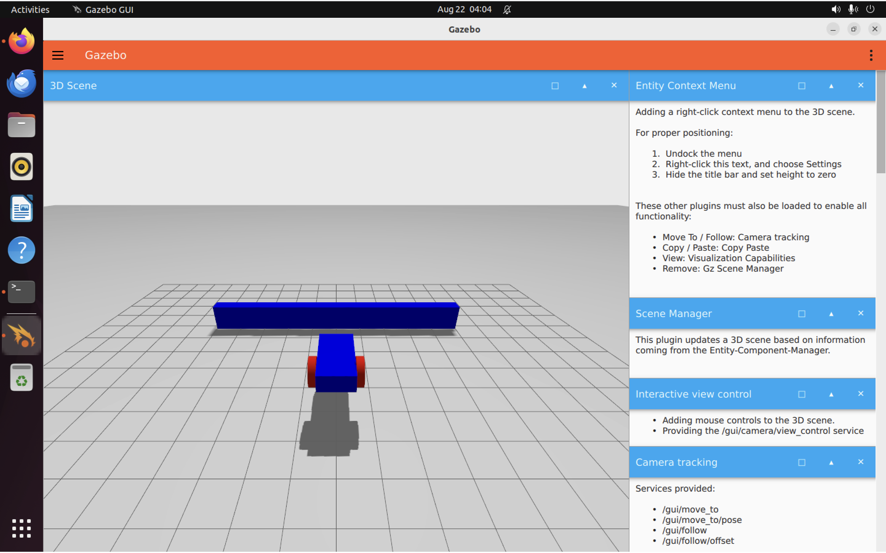
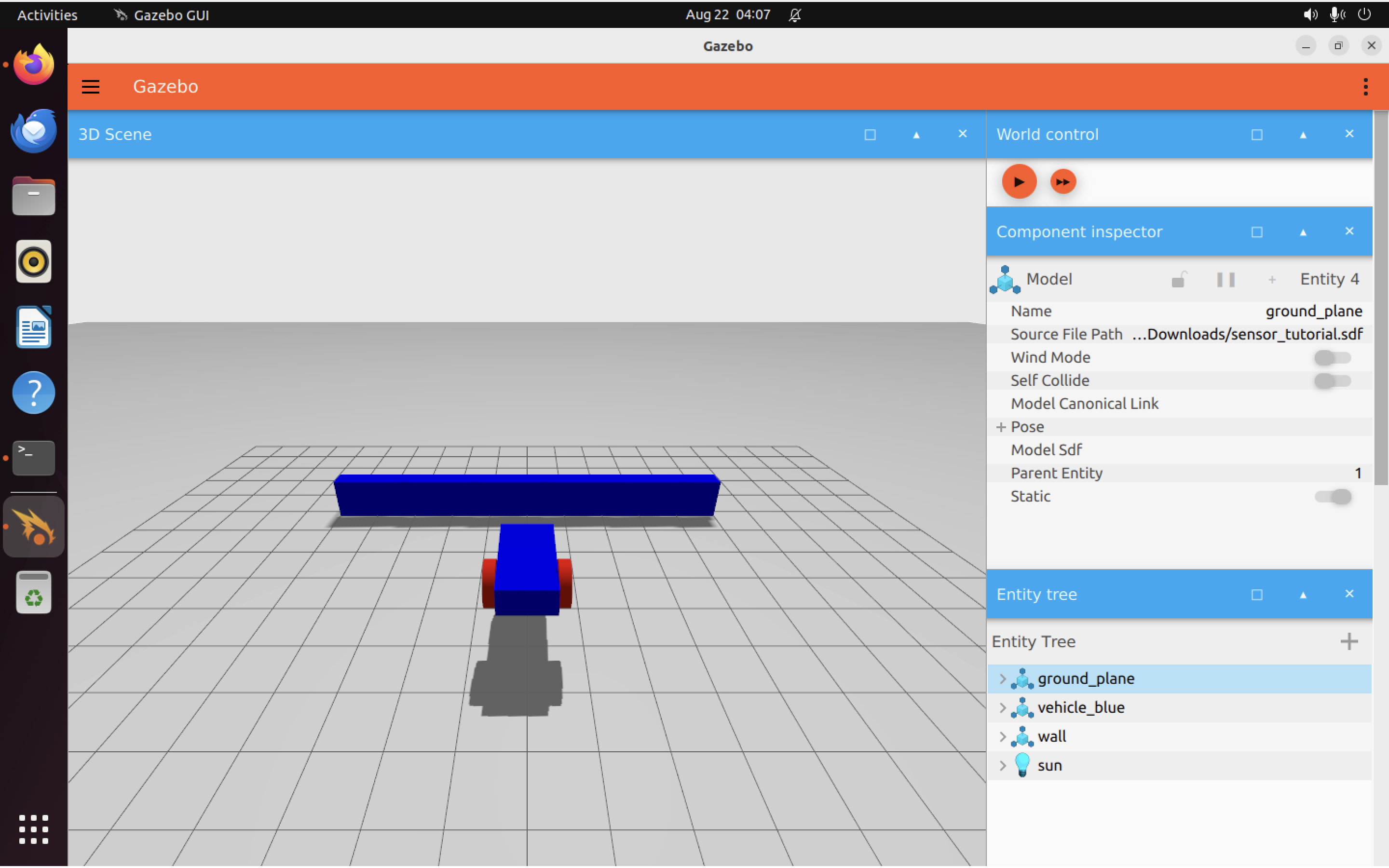
As before, the Gazebo simulator GUI will open up:
In another terminal, run:
ign topic -e -t /imu
Which should output something like this:
header {
  stamp {
    nsec: 1000000
  }
  data {
    key: "frame_id"
    value: "vehicle_blue::chassis::imu_sensor"
  }
  data {
    key: "seq"
    value: "0"
  }
}
entity_name: "vehicle_blue::chassis::imu_sensor"
orientation {
  x: -1.7244575586707343e-29
  y: 1.1367368659168941e-28
  z: 5.5511153141018868e-23
  w: 1
}
angular_velocity {
  x: -3.4489151173414685e-26
  y: 2.273473731833788e-25
  z: 1.1102230628203774e-19
}
linear_acceleration {
  x: 2.7755584900553513e-17
  y: 5.5511153091986593e-17
}
Note: You will need to hit “Play” in the GUI before any output will appear. The Gazebo GUI may open a lot of side-panels, depending on how you have things configured. If you close those side panels (starting from the one in the top right hand corner of the screen), you’ll eventually see the “World control” panel, where there’s a “Play” button you can hit to start the simulation:
The contact sensor Link to heading
In our .sdf file we’ve got a wall, defined like so:
<model name='wall'>
    <static>true</static>
    <pose>5 0 0 0 0 0</pose><!--pose relative to the world-->
    <link name='box'>
        <pose/>
        <visual name='visual'>
            <geometry>
                <box>
                    <size>0.5 10.0 2.0</size>
                </box>
            </geometry>
            <!--let's add color to our link-->
            <material>
                <ambient>0.0 0.0 1.0 1</ambient>
                <diffuse>0.0 0.0 1.0 1</diffuse>
                <specular>0.0 0.0 1.0 1</specular>
            </material>
        </visual>
        <collision name='collision'>
            <geometry>
                <box>
                    <size>0.5 10.0 2.0</size>
                </box>
            </geometry>
        </collision>
    </link>
</model>
It’s just a rectangular box placed in front of our robot (as seen in the screenshots above).
Note: Unlike with our IMU sensor (which is attached to the robot), our contact sensor will actually be attached to the wall.
To do this, we add a plugin for the sensor:
<plugin filename="libignition-gazebo-contact-system.so"
        name="ignition::gazebo::systems::Contact">
</plugin>
And of course we also link the sensor to the wall:
<sensor name='sensor_contact' type='contact'>
    <contact>
        <collision>collision</collision>
    </contact>
</sensor>
Note: Although it isn’t obvious, we are attaching the sensor to the wall here because the box link is named collision. Take a look at the code for the wall box above, to convince yourself of this.
We need one more plugin to get everything working: TouchPlugin. This will send a message when the car touches the wall. This way we can limit the touch sensor such that it only sends a message when our car (vehicle_blue) touches the wall. Using the <namespace> tag, we also tell TouchPlugin where to send messages. They will go to the /wall/touched topic now (per the code above).
Testing out the contact sensor Link to heading
Again, open a terminal and run:
ign gazebo sensor_tutorial.sdf
Open a second terminal and listen to the /wall/touched topic:
ign topic -e -t /wall/touched
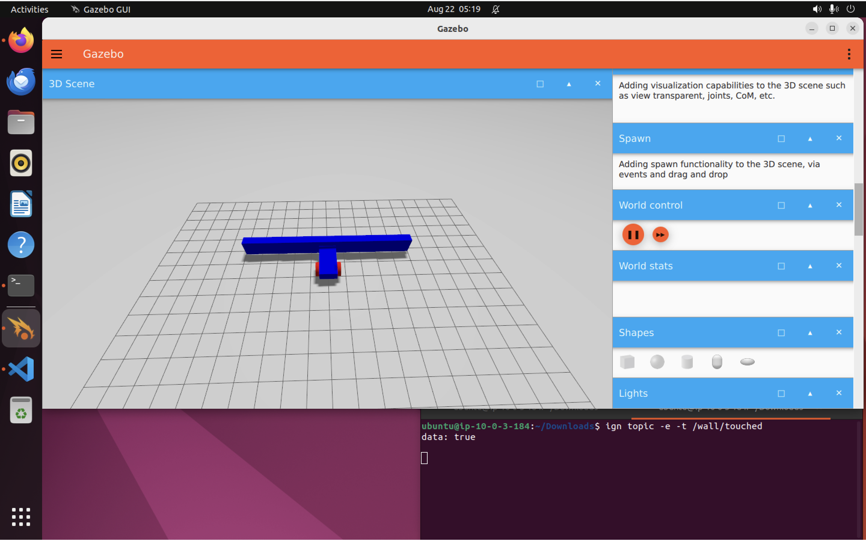
Once again, you’ll have to find the “World control” panel in the Gazebo GUI (I recommend scrolling down to find it rather than closing side panels), and hit “play” before any messages are printed out. You will need to drive your robot forward as well. The “Key Publisher” should already be waiting to receive keystrokes (it’s included as one of the plugins in our .sdf file).
When the robot hits the wall, we should see the following print out from the /wall/touched topic:
data: true
Because our .sdf file contains the following code, two things (see below) are going to happen when we hit the wall:
<plugin filename="libignition-gazebo-triggered-publisher-system.so"
        name="ignition::gazebo::systems::TriggeredPublisher">
    <input type="ignition.msgs.Boolean" topic="/wall/touched">
        <match>data: true</match>
    </input>
    <output type="ignition.msgs.Twist" topic="/cmd_vel">
        linear: {x: 0.0}, angular: {z: 0.0}
    </output>
</plugin>
- The robot will stop moving, because we send
linear: {x: 0.0}, angular: {z: 0.0}to stop the robot - The
/wall/touchedtopic will send outdata: true
Here I am, trying it out:
Note: If you want to see if keypresses are working, you can open an additional terminal and run: ign topic -e -t /keyboard/keypress. Leave the terminal open and return to the Gazebo simulator window. Press a couple of keys. You should see messages showing up in the terminal where you ran ign topic -e -t /keyboard/keypress. The keys you should be using to drive the robot are the arrow keys. The keypress topic will log any keypress, but only the arrow keys are mapped in the .sdl file, so only those keys will move the car (by publishing commands to /cmd_vel).
Awesome! It’s nice to know we can stop ourselves when we hit a wall but…what about avoiding the wall altogether? LIDAR can help us there.
The LIDAR sensor Link to heading
Like the IMU sensor, we’ll fix the LIDAR to the car’s chassis. The code in the .sdf which does this is:
<frame name="lidar_frame" attached_to='chassis'>
    <pose>0.8 0 0.5 0 0 0</pose>
</frame>
We then add a LIDAR plugin, which will collect simulated LIDAR data from our Gazebo world:
<plugin
  filename="libignition-gazebo-sensors-system.so"
  name="ignition::gazebo::systems::Sensors">
  <render_engine>ogre2</render_engine>
</plugin>
The LIDAR itself gets mounted to the chassis using the following <sensor> code:
<sensor name='gpu_lidar' type='gpu_lidar'>"
    <pose relative_to='lidar_frame'>0 0 0 0 0 0</pose>
    <topic>lidar</topic>
    <update_rate>10</update_rate>
    <ray>
        <scan>
            <horizontal>
                <samples>640</samples>
                <resolution>1</resolution>
                <min_angle>-1.396263</min_angle>
                <max_angle>1.396263</max_angle>
            </horizontal>
            <vertical>
                <samples>1</samples>
                <resolution>0.01</resolution>
                <min_angle>0</min_angle>
                <max_angle>0</max_angle>
            </vertical>
        </scan>
        <range>
            <min>0.08</min>
            <max>10.0</max>
            <resolution>0.01</resolution>
        </range>
    </ray>
    <always_on>1</always_on>
    <visualize>true</visualize>
</sensor>
We can make sure it’s all working by starting up our simulation again:
ign gazebo sensor_tutorial.sdf
And listening to the /lidar topic (again, you’ll need to hit “Play” before anything will start showing up on the topic):
ign topic -e -t /lidar
The LIDAR messages have a number of attributes. Here’s the complete list:
message LaserScan
{
  Header header              = 1;

  string frame               = 2;
  Pose world_pose            = 3;
  double angle_min           = 4;
  double angle_max           = 5;
  double angle_step          = 6;
  double range_min           = 7;
  double range_max           = 8;
  uint32 count               = 9;
  double vertical_angle_min  = 10;
  double vertical_angle_max  = 11;
  double vertical_angle_step = 12;
  uint32 vertical_count      = 13;

  repeated double ranges              = 14;
  repeated double intensities         = 15;
}
Each time the LIDAR completes a scan, it will send a message in the above format. Of course, there are a very large number of range and intensity data points, so you might have to dig around in the output before you find a header { field, like this:
header {
  stamp {
    sec: 8
    nsec: 200000000
  }
  data {
    key: "frame_id"
    value: "vehicle_blue::chassis::gpu_lidar"
  }
  data {
    key: "seq"
    value: "82"
  }
}
frame: "vehicle_blue::chassis::gpu_lidar"
world_pose {
  position {
    x: 0.8
    z: 0.5
  }
  orientation {
    w: 1
  }
}
angle_min: -1.396263
angle_max: 1.396263
angle_step: 0.0043701502347417839
range_min: 0.08
range_max: 10
count: 640
vertical_angle_step: nan
vertical_count: 1
This will be followed by a long list of range and intensity values.
Good? Good. Let’s actually use this data to avoid driving into the wall.
Avoiding the wall Link to heading
Now that we have LIDAR data, we can write code to help us avoid the wall. The node will take LIDAR data as input and will output driving commands to the /cmd_vel topic.
Infuriatingly, Gazebo has its own mechanism for creating nodes which is separate from ROS and uses cmake rather than ROS’s colcon build system. Isn’t that just lovely.
The good news is that we don’t need to write this code ourselves. I stole a copy from the Gazebo docs, which is included in the .zip file mentioned at the start of today’s post. The CMakeLists.txt file needed to build that code is included also. From your sensors_tutorial folder, simply run:
mkdir -p build
cp CMakeLists.txt build/
cp lidar_node.css build/
cd build
cmake ..
make lidar_node
Open a terminal and run the new node:
./build/lidar_node
Then, open another terminal and run Gazebo:
ign gazebo sensor_tutorial.sdf
Notice how the robot now moves forward until it is close to the wall, then turns left and resumes going forward until it clears the obstacle. Neat! Here’s a little .gif showing it in action:
Running everything at once Link to heading
Let’s say we don’t want the hassle of having to launch the LIDAR node and the gazebo simulated environment separately. No problem! We can simply write an “ignition file”, which we’ll call sensor_launch.ign. This file is included in the .zip file from the top of this post. It’s quite a small file:
<?xml version='1.0'?>
<ignition version='1.0'>
  <executable name='sensor-world'>
    <command>ign gazebo sensor_tutorial.sdf</command>
  </executable>

  <executable name='lidar_node'>
    <command>./build/lidar_node</command>
  </executable>

</ignition>
As you can see, it will execute the LIDAR node and the simulator together. Let’s try it:
ign launch sensor_launch.ign
The simulator will pop up. If we hit “Play” in “World control”, the robot will start moving right away, because the LIDAR node is already running. Nice!
That’s it for today’s post. In a future post, we’ll look at Gazebo “Actors”, which allow us to include scripted animations, which is handy for testing our agent’s reaction to events beyond its control, and to non-static elements in the world (such as people, cars, or other robots).